Killing machine

The technology of a slaughtering machine and a rotary disc is applied in the field of slaughtering machines, which can solve the problems of affecting the necking action, complex structure, increasing the manufacturing difficulty and cost of the whole animal slaughtering machine, etc., and achieves the effect of eliminating space and simplifying the structure.

Active Publication Date: 2012-08-22
CHANGSHU SLAUGHTERING EQUIP SET
View PDF7 Cites 1 Cited by
  • Summary
  • Abstract
  • Description
  • Claims
  • Application Information

AI Technical Summary

Problems solved by technology

[0004] However, the above-mentioned patent application scheme still has the following shortcoming: in order to prevent the animals from entering the cavity and entering the cage from trying to exit the cage due to fear, Therefore be equipped with a concrete structure at the livestock entrance of prison tube " the animal slaughtering machine driving mechanism of livestock slaughtering machine " recommended by publication number CN101755886A, although the setting of this mechanism can make the slaughtered animal in the prison cylinder forcedly arrive at the killing position , but due to the complex structure of the mechanism, the manufacturing difficulty and cost of the complete machine for livestock slaughtering machines are increased (for details, please refer to paragraph 0004 of the description of CN101755886A), and because the driving mechanism of the livestock to be slaughtered is located at the entrance of the livestock in the cell One end, so that the prison tube increases the distance (ie length) of the width of the driving mechanism of the animal to be slaughtered, and this distance provides a retreat space (room) for the animal to be slaughtered, thereby affecting the head of the animal to stick out of the neck, Ultimately affect the progress of the neck jamming action

Method used


Image

  • Killing machine
  • Killing machine
  • Killing machine

Examples


Embodiment Construction

[0016] In order to enable the examiners of the patent office, especially the public, to understand the technical essence and beneficial effects of the present invention more clearly, the applicant will describe in detail the following in the form of examples, but none of the descriptions to the examples is an explanation of the solutions of the present invention. Any equivalent transformation made according to the concept of the present invention which is merely formal but not substantive shall be regarded as the scope of the technical solution of the present invention.

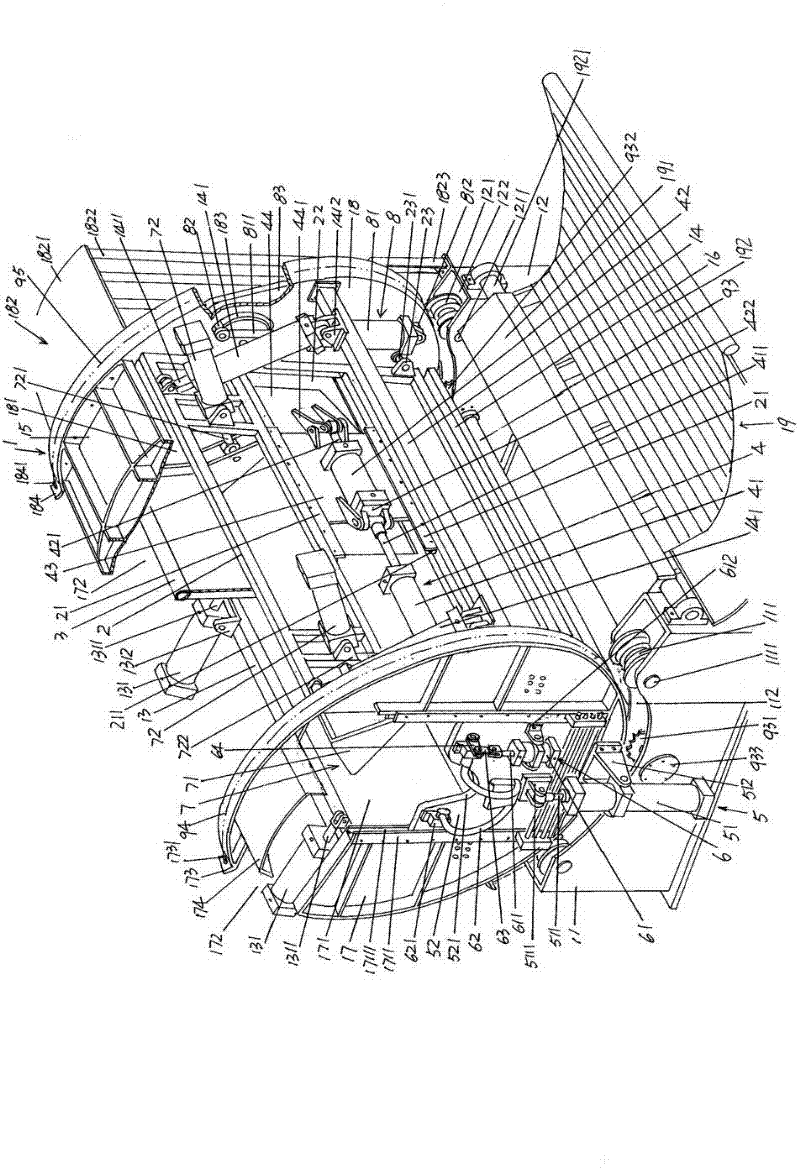
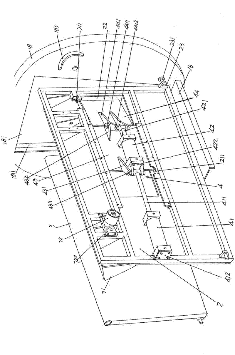
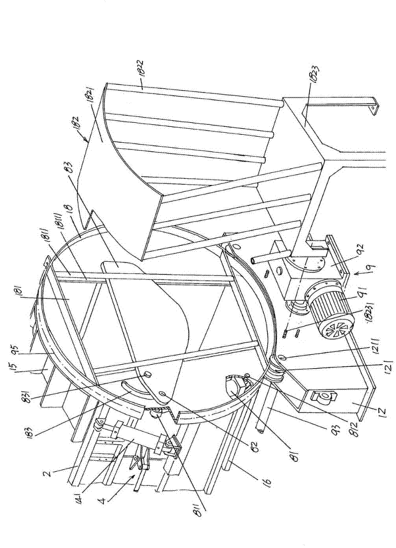
[0017] See figure 1 , provides a cage mechanism 1, which cage mechanism 1 consists of first and second bases 11, 12, first and second beams 13, 14, top and bottom plates 15, 16, left and right rotary discs 17, 18 and livestock receiving trough 19, the first and second bases 11 and 12 are arranged corresponding to each other, and the first and second bases 11 and 12 can be directly placed on the floor of ...


PUM


Abstract

The invention relates to a killing machine and belongs to killing equipment. The killing machine comprises a trapping tube mechanism, a front push plate, a back push plate, a livestock hip driving mechanism, a strangulation mechanism, a livestock head turning mechanism, a killed livestock pushing-out mechanism, a cavity door opening and closing mechanism and a motive power transmission mechanism, wherein the trapping tube mechanism is provided with a left rotary disc and a right rotary disc. The killing machine is characterized in that a pair of guide rails are fixed on the front push plate, a hip pushing plate cavity is arranged in the center position of one end of the front push plate facing one end of the right rotary disc, the livestock hip driving mechanism comprises a first action cylinder, a second action cylinder, a sliding plate and a hip pushing plate, the first action cylinder is fixedly arranged on the front push plate, a first action cylinder post of the first action cylinder is connected with the sliding plate, the sliding plate is glidingly matched with the pair of guide rails, the second action cylinder is arranged on the sliding plate, a second action cylinder post of the second action cylinder is connected with the hip pushing plate, and the hip pushing plate corresponds to the hip pushing plate cavity. The killing machine has the advantages that the structure is simplified, an advancing and retreating moving space of the livestock after entering a cage mechanism is eliminated, and the head part of the livestock is ensured to sufficiently extend out of the left rotary disc, so the neck clamping action is smoothly carried out.

Description

technical field [0001] The invention belongs to the technical field of slaughtering equipment, and in particular relates to a slaughtering machine suitable for slaughtering animals such as cattle, horses, donkeys, mules and camels. Background technique [0002] The slaughter of cattle, horses, donkeys, mules and camels listed above but not limited to is a very troublesome thing, because it needs many people to participate and cooperate to complete it, which is not only time-consuming Time-consuming labor and low slaughter efficiency, and the labor intensity of the staff in the slaughterhouse is high. In order to reduce the labor intensity of the staff, in many slaughterhouses, the animals are usually stunned (knocked down) by electric shock and then slaughtered (bleeding). However, this slaughtering method is not only opposed by the industry, but also by the public. Because it is difficult to drain the blood in the body when slaughtering animals in a comatose state, which w...

Claims


Application Information

Patent Timeline
Patent Type & Authority Applications(China)
IPC IPC(8): A22B1/00
Inventor 张屹周建昌张涛姚毅张雪明
Owner CHANGSHU SLAUGHTERING EQUIP SET
Why Eureka
Try Eureka