Screw terminal and receptacle including same

A screw and terminal technology, applied in the socket field including the screw terminal, can solve the problems of complex bending process, increased cost, difficulty in manufacturing screw terminals, etc.

Inactive Publication Date: 2012-09-12
PANASONIC CORP
View PDF5 Cites 6 Cited by
  • Summary
  • Abstract
  • Description
  • Claims
  • Application Information

AI Technical Summary

Problems solved by technology

Therefore, a complicated bending process is required, which makes it difficult to manufacture the screw te

Method used


Image

  • Screw terminal and receptacle including same
  • Screw terminal and receptacle including same
  • Screw terminal and receptacle including same

Examples


Embodiment )

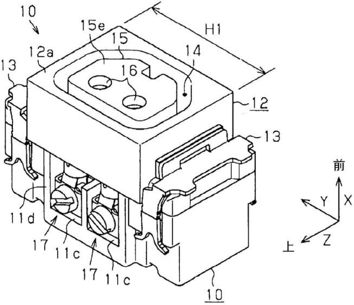
[0111] The socket 10 of the present invention is not limited to the above embodiments, and may be modified as described below. In addition, the following modifications are applicable to the foregoing embodiments, and combinations of various modifications may also be possible.

[0112] In the above-described embodiments, a DC outlet is used as the outlet 10 . However, an AC outlet supplied with AC power may be used as the outlet 10 .

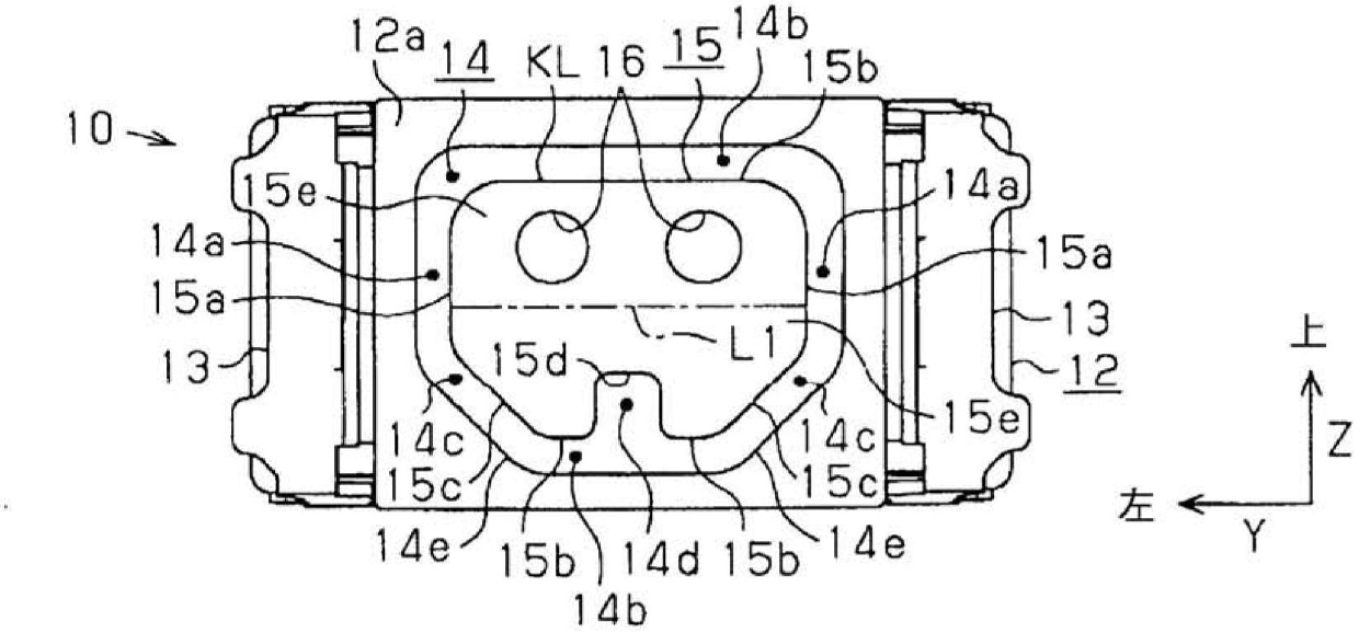
[0113] Although the pin insertion hole 16 is positioned above the center line L1 in the above-described embodiment, the pin insertion hole 16 may be positioned at the same level as the center line L1 or positioned below the center line L1.

[0114] In the above-described embodiment, two inclined grooves 14 c and one extended groove 14 d are provided at the peripheral wall insertion groove 14 . However, the shape of the peripheral wall insertion groove 14 is not limited to the above. For example, if Figure 10 As shown in , the peripheral wall...


PUM


Abstract

A screw terminal includes an electrical wire connecting portion to which an electrical wire is connected by a screw member, and a plug-pin receiver for gripping a plug pin of a plug. The electrical wire connecting portion and the plug-pin receiver are made from a single metal plate. The plug-pin receiver has a tubular shape extending along an insertion direction of the plug pin and the electrical wire connecting portion is formed as a frame body opened along the plug-pin insertion direction. A connecting portion connects the plug-pin receiver to the frame body. The plug-pin receiver has a substantially cylindrical shape, and the electrical wire is firmly pressed against an inner peripheral surface of the frame body by tightening the screw member into the frame body.

Description

technical field [0001] The present invention relates to a screw terminal for supplying electric power from a wire to a plug in a state where plug pins of the plug and the wire are connected to the screw terminal, and a socket including the screw terminal. Background technique [0002] As for the screw terminal, there is known a screw terminal including a pin receiving part for receiving a pin of a plug, and a frame-shaped support part (wire connection unit) into which electric wires are inserted. In this screw terminal, a screw member screwed into a post member is firmly tightened, and an electric wire is firmly pressed against one end of the post member (for example, see Japanese Patent Application Laid-Open No. 2000-243473). [0003] Specifically, as Figure 13A As shown in , a tapped hole 212 forming a screw engagement with a screw member 220 is provided at a peripheral wall 211 of the pillar member 210 . The holding portion 231 of the plug receiving part 230 is inserted...

Claims


Application Information

Patent Timeline
IPC IPC(8): H01R4/36H01R13/03H01R13/11H01R13/64H01R43/00
CPCH01R13/111H01R4/36H01R13/03H01R13/64H01R24/20H01R43/16H01R2103/00
Inventor 加藤一祐上野哲近藤真树滝井利之川本隆司
Owner PANASONIC CORP
Why Eureka
Try Eureka