

Spinning winder
Patent Information
- Authority / Receiving Office
- CN · China
- Patent Type
- Applications(China)
- Current Assignee / Owner
- TMT MACHINERY INC
- Publication Date
- 2012-10-17
Smart Images
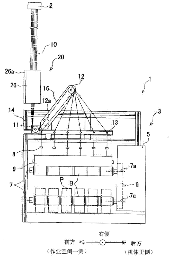
Figure 1 
Figure 2 
Figure 3
Abstract
Description
technical field
[0001] The present invention relates to a spinning winder for winding a plurality of yarns sent out from a spinning section onto a plurality of bobbins mounted on a bobbin holder, respectively. Background technique
[0002] For example, in the spinning winder described in Patent Document 1, a plurality of bobbins are installed in series along the axial direction of the bobbin holder, and above the center of the axial direction of the bobbin holder, a device for heating and stretching a plurality of filaments is provided. multiple heating rollers. The axial direction of these plural heat rollers is perpendicular to the axial direction of the bobbin holder. In addition, the plurality of yarns sent out from the spinning section are sequentially wound on a plurality of heating rollers below, and then respectively wound onto corresponding bobbins.
[0003] However, a plurality of heating rollers are provided in order to sufficiently heat the yarn to a desired te...