Displayer
A display and display panel technology, applied in the direction of instruments, nonlinear optics, optics, etc., can solve the problems of obstructing the frame, narrowing, etc., and achieve the effect of reducing the frame area
- Summary
- Abstract
- Description
- Claims
- Application Information
AI Technical Summary
Problems solved by technology
Method used
Image

Examples
no. 1 example
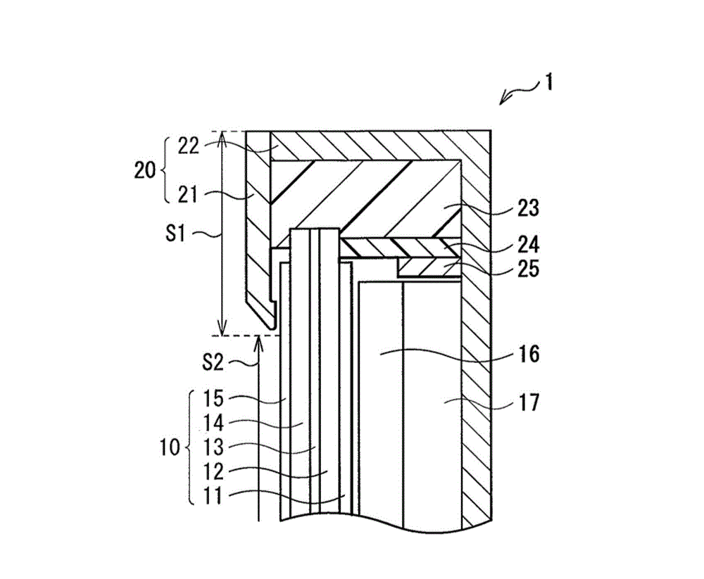
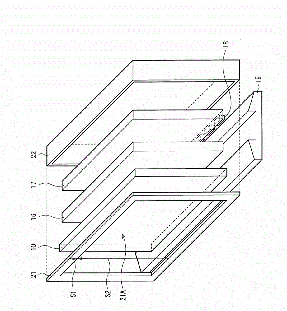
[0022] figure 1 is a diagram showing a sectional configuration of a display (display 1 ) according to the first embodiment of the present disclosure, figure 2 is an exploded perspective view showing the overall configuration of the display 1 . The display 1 is, for example, a liquid crystal display used as a television device. This display 1 has such a structure: wherein, the backlight unit is accommodated in the cabinet 20, and the cabinet 20 includes a front frame body 21 (front member) and a rear cabinet 22 (back member); the backlight unit includes a display panel 10, The optical sheet 16 , the light guide plate 17 , the light source 18 , etc.; the front frame body 21 and the rear cabinet 22 are adhered to each other by an adhesive portion 23 . On one end surface of the light guide plate 17, a plurality of LEDs are arranged as the light source 18, and the light emitted from the light source 18 illuminates the display panel 10 through the light guide plate 17, and is ext...
no. 3 example
[0055] Figure 4 A sectional configuration of a display 3 according to a third embodiment of the present disclosure is shown. The display 3 includes the display panel 10, the optical sheet 16, and the light guide plate 17 accommodated in a case 40, and the display 3 is different from the displays of the first and second embodiments in that the case 40 is configured to include a front glass 41 (front member ), a rear plate 42 (rear member) and a decorative frame 43, and a front glass 41 is provided on the front of the display panel 10 with a sealing layer 44 in between. It should be noted that the front glass 41 (front member), the rear panel 42 (rear member), and the decoration frame 43 are adhered to each other by the adhesive portion 23 .
[0056] As mentioned above, the front glass 41 is a plate-shaped member disposed on the entire front surface of the display panel 10 and has a sealing layer 44 between the display panel 10, and the front glass 41 is made of a high-transpa...
no. 4 example
[0062] Figure 5 A sectional configuration of a display 4 according to a fourth embodiment of the present disclosure is shown. In the display 4, the display panel 10 and the optical sheet 16 are housed in a case 50 using a front glass 51 (front member) provided on the front of the display panel 10 with a sealing layer 44 therebetween, a guide A light panel 52 (back member) and a decorative frame 53 are configured. In the display 4 of the present embodiment, the light guide plate 52 is used as the back member, which is different from the first to third embodiments. It should be understood that the front glass 51 (front member), the light guide plate 52 (rear member), and the decoration member 53 are adhered to each other by the adhesive portion 23 .
[0063] Similar to the third embodiment, the front glass 51 is provided on the front of the display panel 10 and is made of a highly transparent material such as glass, polycarbonate (PC), and plastic with ABS resin added to PC. ...
PUM
 Abstract
Description
Claims
Application Information
PatSnap Eureka turns technology decisions into work you can execute. Powered by our Innovation Knowledge Graph, it runs expert workflows across engineering, life sciences, materials and intellectual property. Get your review-ready output in minutes.


