
Display device

A display and display panel technology, applied in the direction of instruments, televisions, optics, etc., can solve the problems of obstructing the frame, narrowing, etc., and achieve the effect of reducing the frame area

Pending Publication Date: 2019-03-19
SONY CORP
View PDF11 Cites 0 Cited by
  • Summary
  • Abstract
  • Description
  • Claims
  • Application Information

AI Technical Summary

Problems solved by technology

However, in currently available displays, as in Japanese Unexamined Patent Application Publication No. 2010-54718, the front and rear cabinets accommodating the liquid crystal panel are fastened to each other with screws or the like, and therefore must be fixed around the display area. Frame area provides screw fastening area that prevents frame narrowing

Method used


Image

  • Display device
  • Display device
  • Display device

Examples


no. 1 example

[0018] 1. First embodiment (a display in which the front frame and the rear cabinet are adhered to each other with a sealant)

[0019] 2. The second embodiment (a display in which the front frame and the rear panel are connected to each other through the top case and the middle case)

no. 3 example

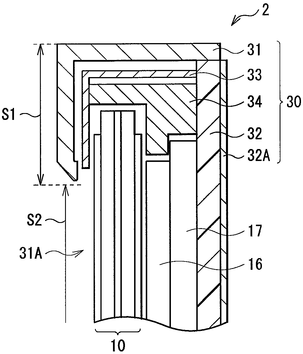
[0020] 3. Third embodiment (a display in which the front glass and the rear plate are adhered to each other with a sealant)

no. 4 example

[0021] 4. Fourth embodiment (a display in which a light guide plate is used as a rear member)

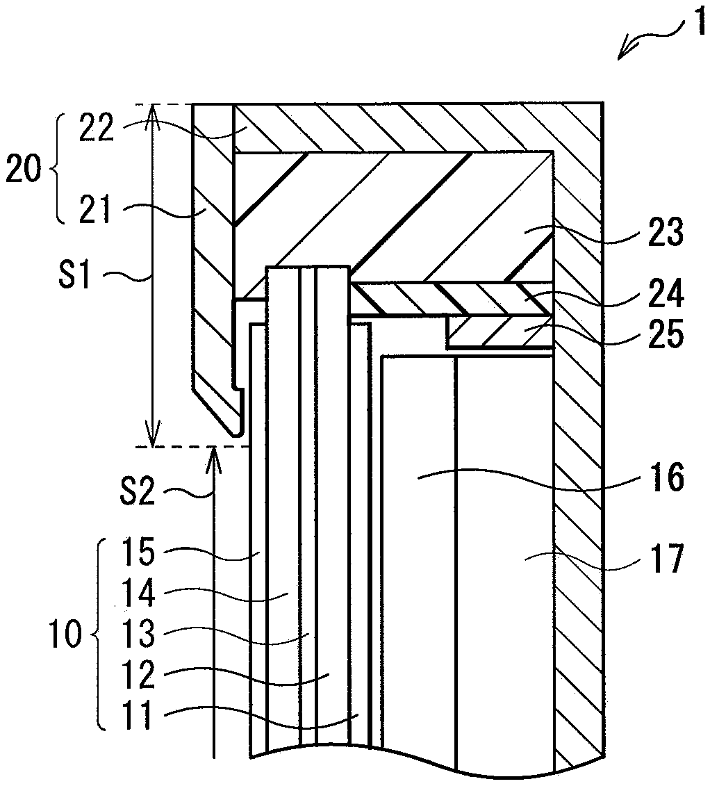
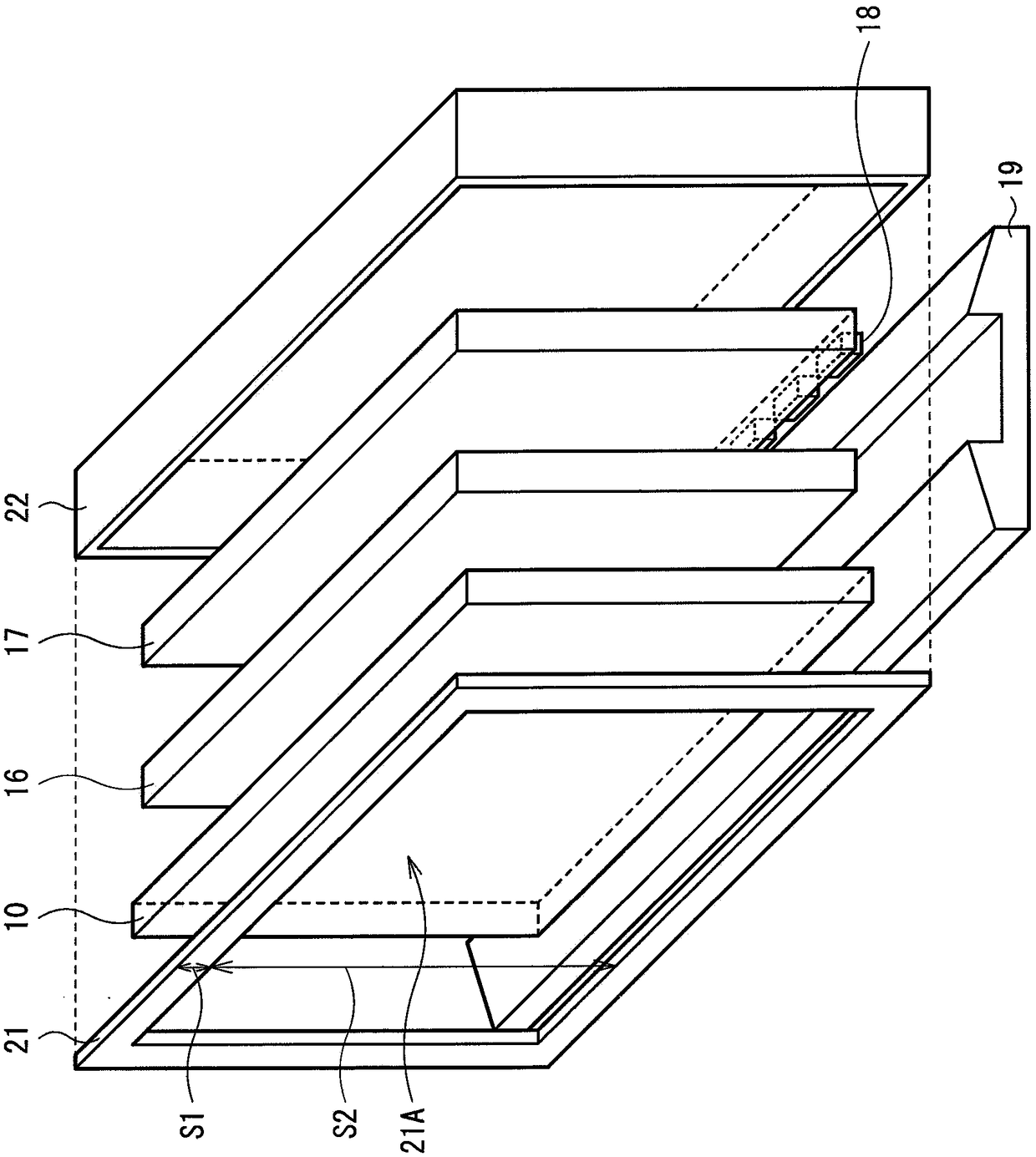
[0022] [1. First embodiment]

[0023] figure 1 is a diagram showing a sectional configuration of a display (display 1) according to the first embodiment of the present disclosure, figure 2 is an exploded perspective view showing the overall configuration of the display 1 . The display 1 is, for example, a liquid crystal display used as a television device. This display 1 has such a structure: wherein, the backlight unit is accommodated in the cabinet 20, and the cabinet 20 includes a front frame body 21 (front member) and a rear cabinet 22 (back member); the backlight unit includes a display panel 10, The optical sheet 16 , the light guide plate 17 , the light source 18 , etc.; the front frame body 21 and the rear cabinet 22 are adhered to each other by an adhesive portion 23 . On one end surface of the light guide plate 17, a plurality of LEDs are arranged as the light source ...


PUM

PropertyMeasurementUnit
thicknessaaaaaaaaaa

Abstract

A display device is disclosed. The display device includes a display panel; a front-face member that is provided on a front face of the display panel and covers at least peripheral part of the displaypanel; a back-face member that is provided on a back face of the display panel and covers at least back-face of the display panel; and an adhesion part for adhesion of the front-face member and the back-face member and covering an outer peripheral part of the display panel.

Description

[0001] This application is a divisional application of the invention with the applicant: Sony Corporation, the filing date: May 17, 2012, the application number: 201210154378.8, and the title: Display. technical field [0002] The present disclosure relates to displays such as television devices. Background technique [0003] There is a demand for thinner and lighter displays, such as displays represented by liquid crystal displays, organic electroluminescence displays, and electrophoretic displays. In a general display, a front chassis such as a front bezel or a top chassis on the display surface side and a rear chassis such as a rear chassis on the back side are fastened to each other by screws or the like, and the display panel is Accommodated between the front chassis and the rear chassis (for example, see Japanese Unexamined Patent Application Publication No. 2010-54718). [0004] In recent years, technological advances in display panels and electronic components have ...

Claims


Application Information

Patent Timeline
Patent Type & Authority Applications(China)
IPC IPC(8): G02F1/1333H04N5/64
CPCG02F1/133308G02F1/133615G02F1/133314G02F1/13332G02F1/133331
Inventor 藤井宽昭向山聪荒木宗也坪井寿宪三宅秀知
Owner SONY CORP
Features
  • Generate Ideas
  • Intellectual Property
  • Life Sciences
  • Materials
  • Tech Scout
  • Unparalleled Data Quality
  • Higher Quality Content
  • 60% Fewer Hallucinations
Learn More