
Battery locking mechanism

A battery lock and locking technology, which is applied to electric power units, power units, transportation and packaging, etc., can solve the problems of users waiting for a long time for charging and reducing battery life.

Active Publication Date: 2012-12-12
SHENZHEN JINGZHI MACHINE
View PDF6 Cites 33 Cited by
  • Summary
  • Abstract
  • Description
  • Claims
  • Application Information

AI Technical Summary

Problems solved by technology

If the mode of not changing batteries is adopted, the disadvantages are that firstly, the user waits for a long time for charging; secondly, due to reasons such as improper charging and lack of maintenance, the battery life may drop sharply

Method used


Image

  • Battery locking mechanism
  • Battery locking mechanism
  • Battery locking mechanism

Examples


Embodiment Construction

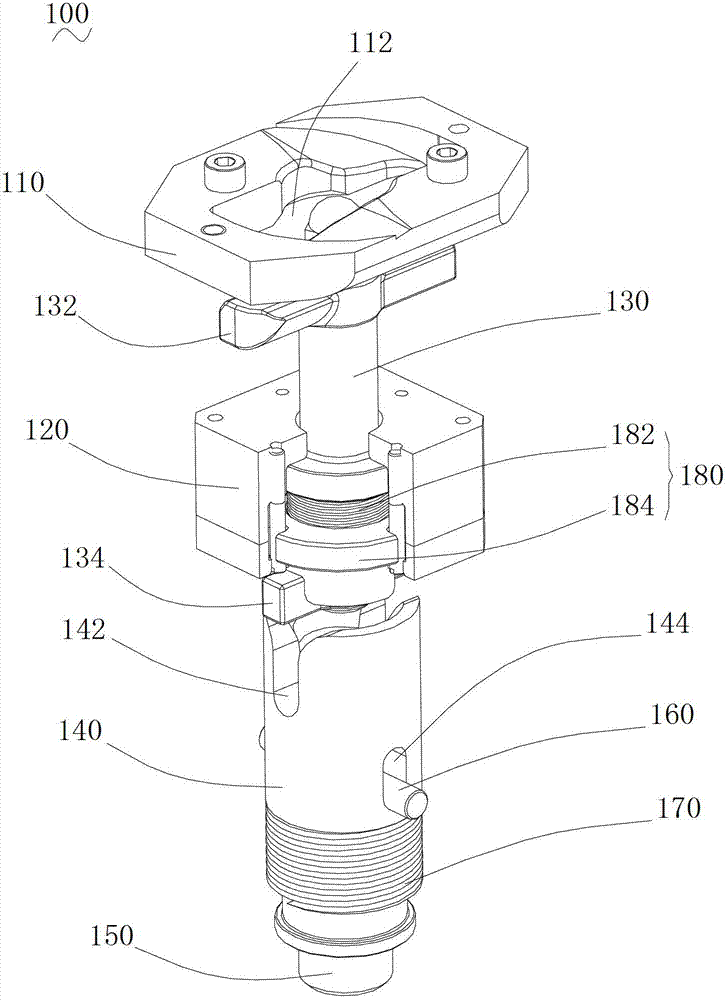
[0020] Please refer to Figure 1 to Figure 5 , The battery locking mechanism 100 of this embodiment is used in the electric vehicle chassis battery replacement system, and can quickly and reliably realize the fixing and separation between the battery and the electric vehicle chassis.

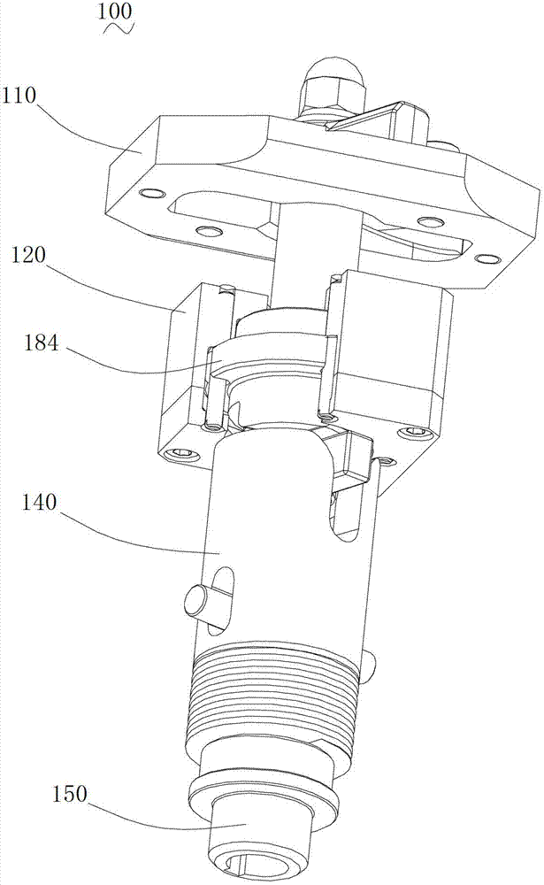
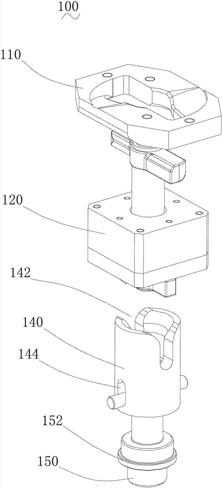
[0021] Please refer to Figure 1 to Figure 3 , the battery locking mechanism 100 of this embodiment includes a hanging buckle 110 , a twist lock holding box 120 , a central pull shaft 130 , a manipulator 140 , an input shaft 150 , a fixing pin 160 , a manipulator return spring 170 and a turn lock part 180 .

[0022] The buckle 110 is fixed on the chassis of the electric vehicle and is provided with a holding groove 112 . The twist lock retaining box 120 is bolted to the edge of the battery.

[0023] The central pulling shaft 130 is rotatably installed in the twist lock holding box 120 , one end of the central pulling shaft 130 is provided with a first hanging pin 132 , and the other end is pro...


PUM


Abstract

The invention relates to a battery locking mechanism which is used for a power-exchanging system of an electric car chassis. The battery locking mechanism comprises a hanging buckle, a rotary lock maintaining box, a central pull shaft and a mechanical arm, wherein the hanging buckle is fixed on the electric car chassis and is provided with a holding slot; the rotary lock maintaining box is fixed on a battery; the central pull shaft is rotatably mounted in the rotary lock maintaining box; a first hanging pin is arranged at one end of the central pull shaft; the first hanging pin can enter the holding slot and then is locked with the hanging buckle after the first hanging pin is rotated; after the first hanging pin is reversely rotated, the first hanging pin and the hanging buckle are unlocked; a second hanging pin is arranged at the other end of the central pull shaft; the mechanical arm is arranged in a lifting form relative to the rotary lock maintaining box and is provided with a locking slot; the locking slot is matched with the second hanging pin; and when the mechanical arm is rotated, the central pull shaft is driven to rotate through the locking slot. According to the battery locking mechanism, the central pull shaft is driven to rotate by the mechanical arm, so as to lock the first hanging pin on the hanging buckle. During unlocking, the central pull shaft is driven to reversely rotate by the mechanical arm.

Description

technical field [0001] The invention relates to the field of electric vehicles, in particular to a battery locking mechanism used in a battery swapping system for an electric vehicle chassis. Background technique [0002] Due to air pollution, global warming, shortage of oil resources and other reasons, new energy vehicles represented by electric vehicles have become a research hotspot today. Pure electric vehicles have technical advantages such as no pollution, low noise, and high energy efficiency. However, pure electric vehicle technology is still immature, mainly because the development of electric vehicles is restricted by battery technology. Electric vehicle charging schemes can be divided into non-swapping mode and battery-swapping mode. If the battery replacement mode is adopted, the disadvantages are: first, the user waits for a long time for charging; second, due to improper charging and lack of maintenance, the battery life may drop sharply. To sum up, the devel...

Claims


Application Information

Patent Timeline
Patent Type & Authority Applications(China)
IPC IPC(8): B60K1/04
Inventor 沈浩王俊梁虎管大功谢勇
Owner SHENZHEN JINGZHI MACHINE
Learn More