
Force measurement device of tensioner

A force measuring device and tensioner technology, applied in the mechanical field, can solve problems such as high cost, limited use conditions, and complex structure, and achieve the effects of compact structure, improved stability, and high practical value

Active Publication Date: 2012-12-19
ZHEJIANG TOPSUN LOGISTIC CONTROL CO LTD
View PDF9 Cites 0 Cited by
  • Summary
  • Abstract
  • Description
  • Claims
  • Application Information

AI Technical Summary

Problems solved by technology

It can be seen that although the above-mentioned tensioner can clearly display the tension force, the sensor, display device, etc. must be equipped with a power supply to work normally. It is not only complex in structure, but also has a high cost.
There are also restrictions on the conditions of use. If the power supply: for example, the battery is dead, it will not be able to test the tension normally.

Method used


Image

  • Force measurement device of tensioner
  • Force measurement device of tensioner
  • Force measurement device of tensioner

Examples


Embodiment Construction

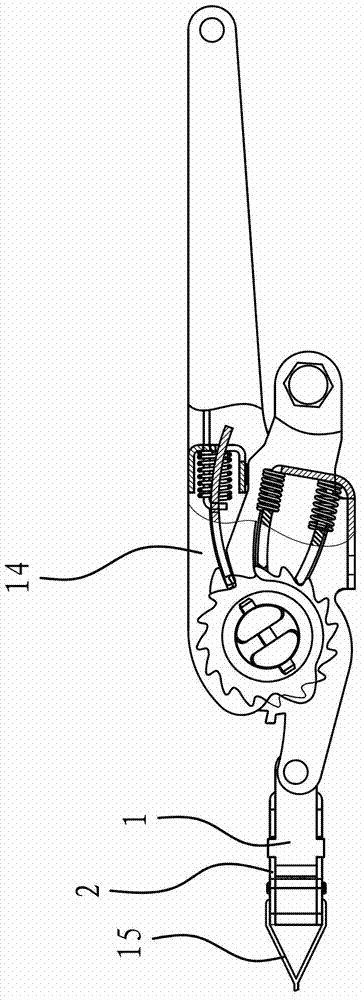
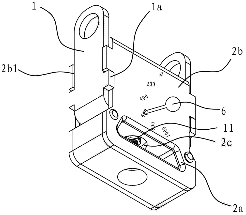
[0045] Such as figure 1 As shown, the force measuring device of the tensioner includes a movable part 1 and a fixed part 2 , the fixed part 2 is used to be fixedly connected with the tensioner 14 , and the movable part 2 is used to be connected with the binding belt 15 . During the binding operation of the tensioner, the operator can know the current binding force through this device.

[0046] There is a guide structure between the fixed part 1 and the movable part 2, and the movable part 2 is translated relative to the fixed part 1 through the guide structure.

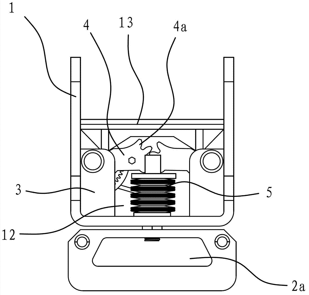
[0047] The fixing part 1 is U-shaped, and the U-shaped notch of the fixing part 1 is fixedly connected with a fixing seat 3 , and the inner end of the load-bearing lever 4 is hinged on the fixing seat 3 .

[0048]The movable part 2 includes a guide part 2b and a connecting part 2a for linking with the binding band 15, the guiding part 2b is located at the U-shaped notch of the fixed part 1, the connecting part 2a is ...


PUM


Abstract

The invention provides a force measurement device of a tensioner, belonging to the technical field of machinery and solving the problems of complex structure, higher cost and low stability of the traditional common tensioner. The force measurement device of the tensioner comprises a fixed part and a movable part, wherein the fixed part is fixedly connected with the tensioner; the movable part is used for connecting with a binding belt; a guide structure which can enable the movable part to translate relative to the fixed part is positioned between the fixed part and the movable part; the fixed part is internally provided with a load-bearing lever, and the inner end of the load-bearing lever is articulated with the fixed part; a spring is arranged between the load-bearing lever and the movable part; the outer side of the movable part is provided with a plurality of pointers which are digitally identified and can swing; the load-bearing lever is connected with the pointers, when the load-bearing lever is only subjected to the elasticity action of the spring, the load-bearing lever drives the points to point to the zero scale position of scale identification, and the outer end of the load-bearing lever has a trend of supporting against the movable part under the elasticity action of the spring.

Description

technical field [0001] The invention belongs to the technical field of machinery, and relates to a tensioner for binding goods, in particular to a force measuring device in the tensioner. Background technique [0002] Tensioners are widely used in the logistics industry, through which the goods are firmly bound so that the goods will not loosen or fall off during transportation. [0003] Whether the existing tensioner is in use depends on the operator's experience to determine whether the goods are bound firmly. The binding force of the goods after binding cannot be intuitively understood. [0004] In order to solve the above problems, the Chinese patent publication No. CN201707163U provides "a binding force tester for a tensioner", which includes a columnar force-measuring piece, and the force-measuring piece has a In the connection part of the connection, the side part of the force measuring member has a notch along its axial direction and elastic fins are formed on both...

Claims


Application Information

Patent Timeline
IPC IPC(8): G01L5/06
Inventor 朱正中
Owner ZHEJIANG TOPSUN LOGISTIC CONTROL CO LTD
Learn More