Ship inverter system

A technology for inverters and ships, applied in control systems, output power conversion devices, electrical components, etc., can solve the problems of complicated configuration and high proportion of space occupied in the ship, and achieve the optimization of the number of units, space saving, and reduction of Effect of magnetizing inrush current

Inactive Publication Date: 2012-12-19
NISHISHIBA ELECTRIC
View PDF8 Cites 2 Cited by
  • Summary
  • Abstract
  • Description
  • Claims
  • Application Information

AI Technical Summary

Problems solved by technology

In addition, the actual situation is that the three-phase three-winding transformer 10 occupies a high proportion of space in the ship, and it takes a lot of effort to configure it.

Method used


Image

  • Ship inverter system
  • Ship inverter system
  • Ship inverter system

Examples


Embodiment approach 1

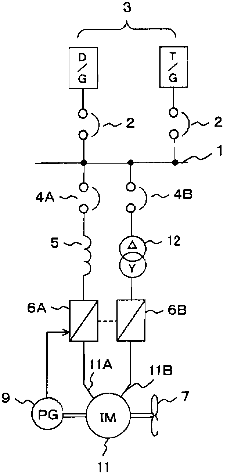
[0027] refer to figure 1 Embodiment 1 of the present invention will be described with reference to the configuration diagram of the marine inverter system shown.

[0028] (structure)

[0029] exist figure 1 In this embodiment 1, the marine inverter system and Figure 5 The difference of the marine inverter system shown in is that instead of the three-phase three-winding transformer 10, an AC reactor 5 and a three-phase single-winding transformer (△-Y type) 12 are used, and the power supply of the AC reactor 5 The side terminal is connected to the inboard bus 1 via the load-side circuit breaker 4A, and the load-side terminal is connected to the power-side terminal of the inverter 6A, thereby constituting the first power supply system; and, the power-side terminal of the three-phase single-winding transformer 12 It is connected to the inboard bus 1 via the load-side circuit breaker 4B, and the load-side terminal is connected to the power-side terminal of the inverter 6B, th...

Embodiment approach 2

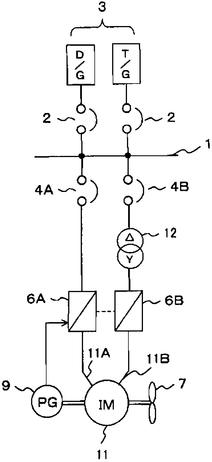
[0036] Next, refer to figure 2 Embodiment 2 of the present invention will be described with reference to the system configuration diagram shown.

[0037] exist figure 2 In this Embodiment 2, the difference from the above-mentioned Embodiment 1 is that, from figure 1 The system shown removes the AC reactor 5 to directly connect the power supply side terminal of the main side inverter 6A to the bus 1 in the ship, and the other structures are the same as figure 1 same.

[0038] In the case of Embodiment 2, although the harmonic suppression effect is slightly inferior to that of Embodiment 1 due to the removal of the AC reactor 5, the reduction effect of the equipment cost and the space saving in the ship due to the removal of the AC reactor 5 The effect of transformation is very high.

Embodiment approach 3

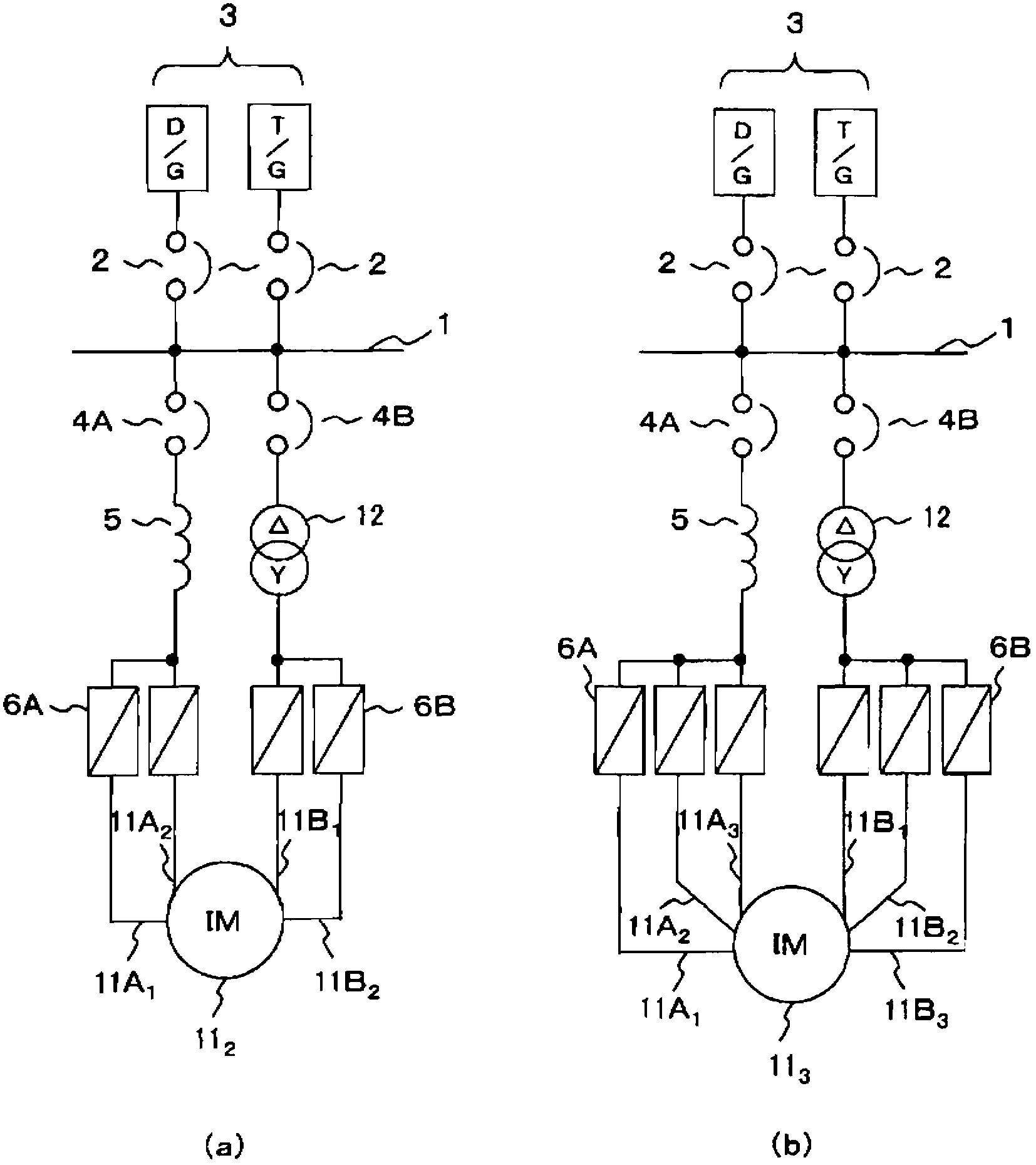
[0040] In the above embodiment 1 ( figure 1 ) and Embodiment 2 ( figure 2 ), a double-winding motor is used as the multi-winding motor 11, but the multi-winding motor is not limited to the double-winding type, and other multi-winding motors may be used.

[0041] image 3 (a) is the application of four-winding motor 11 2 The system structure diagram of the case, image 3 (b) is the application of six-winding type motor 11 3 The system structure diagram of the case. In addition, in image 3 The propeller 7, the speed detector 9, etc. are omitted in . exist image 3 In either of the systems (a) and (b), the stator windings and the inverters of the propulsion motor 11 are divided into two groups, whereby electric power is supplied to the propulsion motor using two systems.


PUM


Abstract

A ship inverter system can reduce magnetizing inrush current without special transformer, so as to optimize volume and number of generators disposed in the ship and save space in the ship. When the voltage through a frequency conversion by a plurality of inverters connected to the inboard bus is supplied to a ship inverter system of a plurality of stator windings wound on a propulsion motor, the stator windings and the inverters of the propulsion motor is divided into two groups, wherein a first group of the stator windings of the propulsion motor are connected the a load side of a first group of the inverters, a power supply side of the first group of the inverters are connected to the inboard bus through a common AC reactor, a second group of the stator windings of the propulsion motor are connected to a load side of a second group of the inverters, and a power supply side of the second group of the inverters are connected to the inboard bus through a common three-phase single-winding transformer, wherein a voltage phase of a primary side and a secondary side of the three-phase single-winding transformer are shifted by 30 degrees.

Description

technical field [0001] The present invention relates to an inverter system for a ship which suppresses the flow of harmonic components generated from an inverter into a bus in the ship. Background technique [0002] As a system for controlling an AC motor with an inverter, the systems disclosed in Patent Documents 1 and 2 can be cited. [0003] Figure 4 It is a simplified system configuration diagram of the conventional inverter systems disclosed in Patent Documents 1 and 2 above. [0004] exist Figure 4 Among them, 1 is an inboard bus, which is connected to various alternators 3 such as a diesel generator (D / G) and a gas turbine generator (T / G) via a power source side circuit breaker 2 to receive power supply. Further, a propulsion motor 8 for driving the propeller 7 is connected to the inboard bus 1 via a load-side circuit breaker 4, an AC reactor 5, and an inverter 6. 9 is the detection of the rotational speed of the propulsion motor 8 to control the inverter 6. A spe...

Claims


Application Information

Patent Timeline
Patent Type & Authority Applications(China)
IPC IPC(8): H02P27/06H02M1/12
Inventor 山本和彦
Owner NISHISHIBA ELECTRIC
Why Eureka
Try Eureka