Sputtering device

A sputtering device and sputtering method technology, applied in sputtering coating, vacuum evaporation coating, coating, etc., can solve the problems of volume increase, building configuration, complex vacuum sealing structure, and rising manufacturing costs. Achieve the effects of reducing the occurrence of poor film formation, reducing the occurrence of particles, and increasing the amount of film formation

Active Publication Date: 2019-04-02
ULVAC INC
View PDF12 Cites 1 Cited by
  • Summary
  • Abstract
  • Description
  • Claims
  • Application Information

AI Technical Summary

Problems solved by technology

In order to be able to maintain the vacuum-tight state in such a device, there are problems that the vacuum-tight structure is complicated, the manufacturing cost also increases, and the volume of the whole device may also increase.
In particular, when the volume of an apparatus for sputtering processing of large substrates increases, the amount of increase in volume will even affect the layout of the building where the processing apparatus is installed.

Method used


Image

  • Sputtering device
  • Sputtering device
  • Sputtering device

Examples


Embodiment Construction

[0060] Next, a sputtering device according to an embodiment of the present invention will be described based on the drawings. In addition, the present embodiment is specifically described for better understanding of the gist of the present invention, and does not limit the present invention unless otherwise specified.

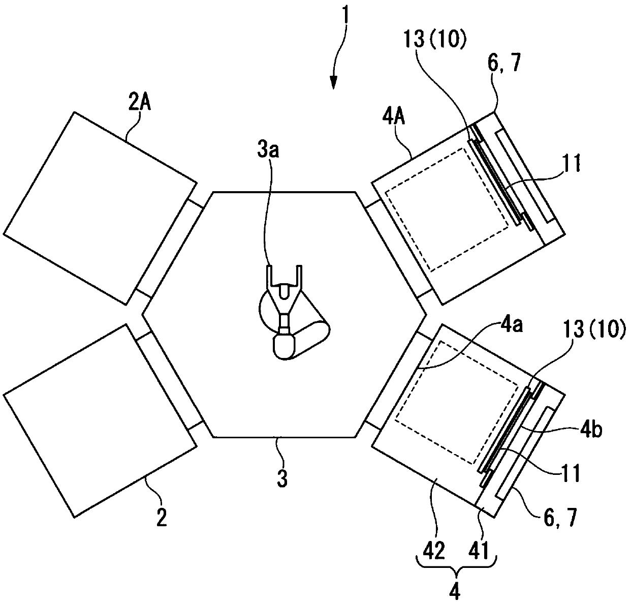
[0061] figure 1 is a schematic plan view showing the sputtering device according to the present embodiment, and figure 1 Among them, reference numeral 1 is a sputtering device.

[0062] The sputtering device 1 according to the present embodiment is used for a substrate to be processed formed of glass or resin, for example, when a TFT (Thin film transistor, thin film transistor) is formed on a substrate formed of glass or the like in a manufacturing process of a liquid crystal display. Reciprocating vacuum processing equipment that performs heat processing, film formation processing, etching processing, etc. in a vacuum environment.

[0063] Such as figur...


PUM


Abstract

A sputtering device according to the present invention is a device which uses a sputtering method to form a film on a to-be-processed substrate, the sputtering device being provided with: a vacuum chamber; a target provided on the surface of a cathode that is provided in the vacuum chamber; a substrate holding part which is provided in the vacuum chamber to face the target and on which a to-be-processed substrate is installed; and a swinging part that allows the substrate holding part to swing relative to the target. A swinging region of the to-be-processed substrate in the substrate holding part is set smaller than an erosion region of the target.

Description

technical field [0001] The present invention relates to a sputtering device, in particular to a technique suitable for use in film formation with a magnetron cathode. [0002] This application claims priority based on Patent Application No. 2017-126261 filed in Japan on June 28, 2017, and uses the content thereof here. Background technique [0003] As described in Patent Document 1, in a film forming apparatus having a magnetron cathode, a system is known in which a magnet is moved relative to a target in order to improve the utilization efficiency of the target or the like. [0004] In addition, as in the technique disclosed in Patent Document 1, it is also known to shake the cathode and the target with respect to the film-forming substrate in addition to the movement of the magnet in order to improve the film-forming uniformity. [0005] In an apparatus that oscillates a magnet or a cathode like the technique disclosed in Patent Document 1, dust generated by the oscillati...

Claims


Application Information

Patent Timeline
Patent Type & Authority Applications(China)
IPC IPC(8): C23C14/34H01L21/363
CPCC23C14/505C23C14/3407C23C14/564C23C14/34C23C14/35C23C14/50
Inventor 金子俊则大野哲宏
Owner ULVAC INC
Why Eureka
Try Eureka