Monitoring Systems Using Optical Reflectometers

A technology of optical reflection and monitoring system, which is applied in the direction of reflectometer, transmission system, and optical instrument test for detecting backscattered light in the time domain, and can solve problems such as power and signal-to-noise ratio limitations

Inactive Publication Date: 2016-01-20
ALCATEL LUCENT SAS
View PDF8 Cites 0 Cited by
  • Summary
  • Abstract
  • Description
  • Claims
  • Application Information

AI Technical Summary

Problems solved by technology

However, such an approach is mainly limited by power and signal-to-noise ratio

Method used


Image

  • Monitoring Systems Using Optical Reflectometers
  • Monitoring Systems Using Optical Reflectometers
  • Monitoring Systems Using Optical Reflectometers

Examples


Embodiment Construction

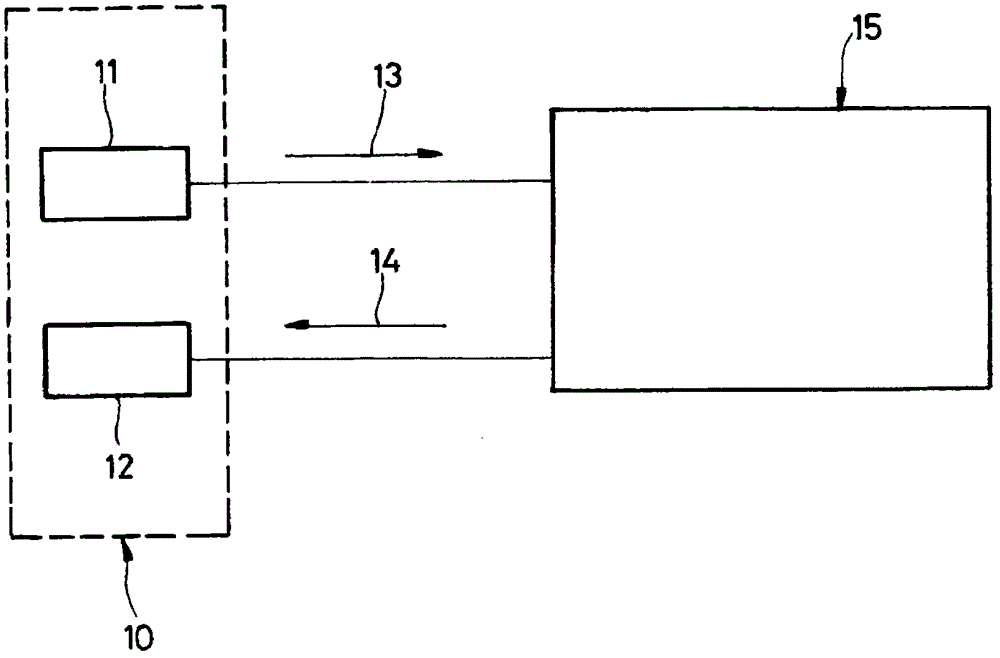
[0037] refer to figure 1 , the optical reflectometer measurement device 10 is coupled to a system 15 in which the measurements have to be obtained. The device 10 includes: an excitation module 11 coupled to the system 15 so as to inject optical excitation signals into the system on a plurality of wavelength channels as indicated by arrow 13; Receive backscattered optical signals corresponding to the excitation signals. The coupling of the modules 11 and 12 to the system 15 may be made by power couplers or any other suitable means, such as optical circulators.

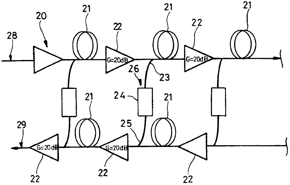
[0038] System 15 may comprise any optical system, especially an optical communication system, such as a passive optical network, or a part of such a system. In the remainder of this document, an embodiment is described in more detail in which system 15 is composed in part of Figure 6 The two-way amplified WDM transmission line 20 depicted in the composition. The bidirectional line 20 can be used for longer distance...


PUM


Abstract

A method for monitoring a system using an optical reflectometer comprising: receiving a first optical response signal from the system in response to a first optical excitation signal, the first excitation signal carrying a first sequence of values ​​(A), responding Based on a second optical excitation signal, receiving a second optical response signal from the system, the second excitation signal carrying a second sequence of values ​​(|A, B), and determining the difference between the optical response signal and the sequence of values Correlation between in order to detect outliers of the system. The first and second stimulus signals are simultaneously transmitted within the optical system by wavelength division multiplexing on separate carrier wavelengths (λ0, λ1), and the first and second response signals are simultaneously received on said separate carrier wavelengths.

Description

technical field [0001] The present invention relates to the field of optical reflectometry measurements, in particular to measurements in which an optical excitation signal carrying a sequence of values ​​is transmitted within a system to be monitored so that the Correlate the scatter signal to monitor the system for anomalies. Background technique [0002] In optical systems, especially in telecommunication systems, optical reflectometry can locate anomalies such as heterogeneities, discontinuities, cracks, interfaces and other refractive index variations as they affect the backscatter of the optical signal. For these phenomena, a measurement technique known as Optical Time Domain Reflectometry (OTDR) was established. The purpose of the OTDR technique is to estimate the impulse response of the system to be monitored by sending an excitation signal into the system and measuring the backscatter response signal. can be approximated using the Dirac distribution Impulse exci...

Claims


Application Information

Patent Timeline
Patent Type & Authority Patents(China)
IPC IPC(8): G01M11/00H04B10/071
CPCG01M11/3118G01M11/3127H04B10/071G01M11/00
Inventor C·多里策G·沙莱P·特兰
Owner ALCATEL LUCENT SAS
Why Eureka
Try Eureka