Shunt circuit linearity insulating circuit apparatus

A technology of isolation circuit and photoelectric isolation circuit, which is applied in the direction of measuring devices, DC isolation amplifiers, voltage/current isolation, etc., and can solve the problems of complex transformers, magnetization, and low common-mode rejection of photoelectric isolation circuits.

Inactive Publication Date: 2007-05-16
李君
View PDF1 Cites 24 Cited by
  • Summary
  • Abstract
  • Description
  • Claims
  • Application Information

AI Technical Summary

Problems solved by technology

[0018] The second difficulty is that the delays of the low-channel isolation channel and the high-channel isolation channel are inconsistent
However, the transformer in this method is more complicated, and when the low-circuit and high-circuit signal amplitudes are not well matched, DC magnetic flux may appear in the transformer core, which will cause the core to be saturated or magnetized. Furthermore, its photoelectric isolation circuit Low common-mode rejection at high frequencies

Method used


Image

  • Shunt circuit linearity insulating circuit apparatus
  • Shunt circuit linearity insulating circuit apparatus
  • Shunt circuit linearity insulating circuit apparatus

Examples


Embodiment 1

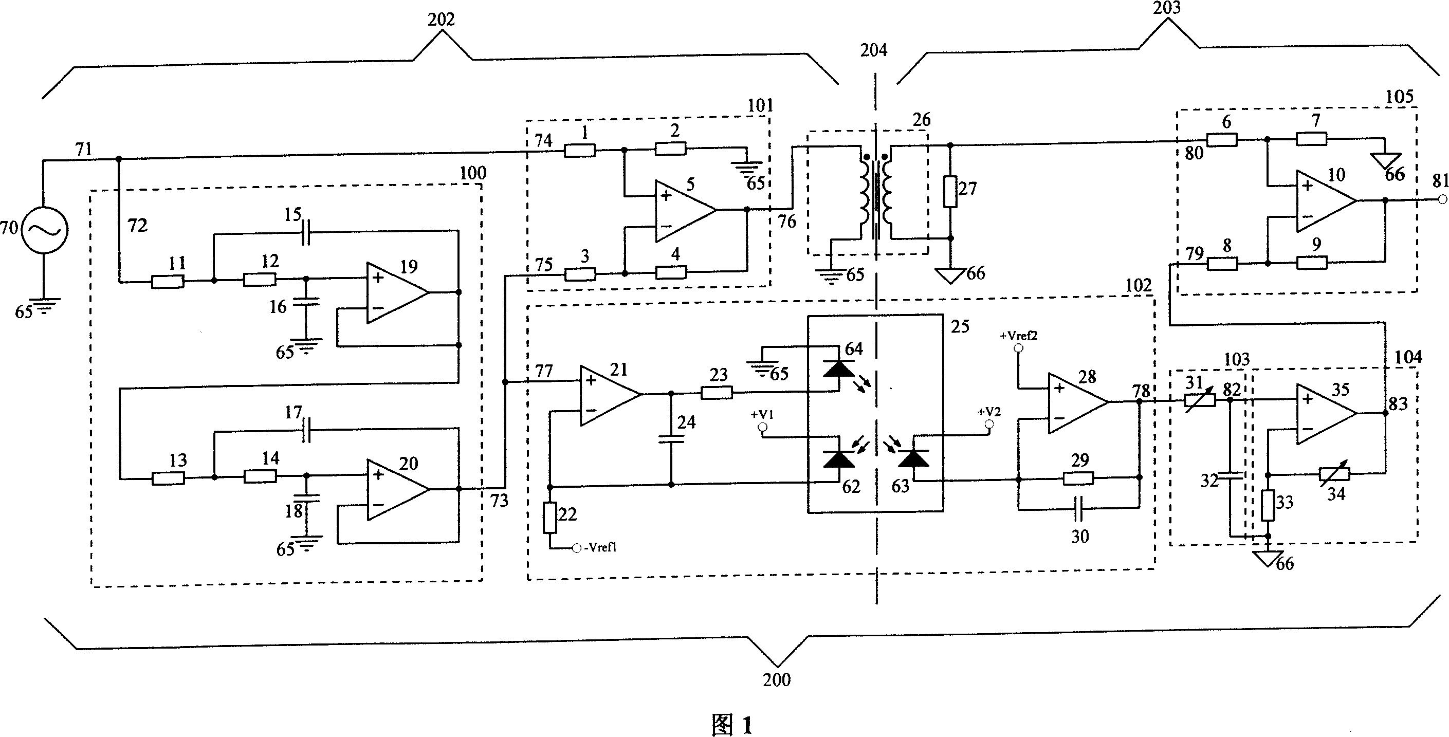
[0036] As shown in Figure 1, all components in the figure are connected by electronic components in the dotted line frame. The device of the present invention is the shunting linear isolation circuit device 200 (hereinafter referred to as the device 200) consisting of a low-pass filter 100 (hereinafter referred to as the filter 100), a subtractor 101, a transformer 26, a linear photoelectric isolation circuit 102 (hereinafter referred to as an optocoupler) Circuit 102), time constant adjustment circuit 103 (hereinafter referred to as circuit 103), low-path gain adjustment circuit 104 (hereinafter referred to as circuit 104) and signal combination circuit 105 (hereinafter referred to as combiner 105). The signal under test 70 is connected to an input 71 of the device 200 . The input 71 of the device 200 is connected to the input 72 of the filter 100 and to the positive input 74 of the subtractor 101 . The output terminal 73 of the filter 100 is not only connected to the negati...

Embodiment 2

[0057] The circuit in Figure 1 has a high common-mode rejection ratio to DC and low-frequency common-mode interference, but it has a small common-mode rejection ratio to high-frequency common-mode signals. In order to further improve the high-frequency common-mode rejection ratio of the shunt linear isolation circuit device, the circuit in Figure 1 can be changed to a differential form. Figure 8 shows an example of a differential form. In Fig. 8, low-pass filter 100, subtractor 101, transformer 26, optocoupler circuit 102, time constant adjustment circuit 103, low path gain adjustment circuit 104 and signal combining circuit 105 are the same as the embodiment shown in Fig. 1 , and will not repeat them here. The difference is that the driving and receiving of the transformer are changed to differential driving and differential receiving, and the photoelectric isolation circuit adds a set of circuits exactly the same as the optocoupler circuit 102, that is, the optocoupler circ...


PUM


Abstract

This invention relates to router linear isolation circuit device, which comprises transducer, photoelectricity isolation amplifier and signal combination device and one abstract frequency and one time parameter adjust circuit, wherein, the abstract frequency device is composed of low band filter and high band filter and one abstract device; the input signal is connected to low band filter or high band filter input end and first input end of abstract device; the low band and high band filter output end is connected to other end of abstract device.

Description

Technical field: [0001] This invention relates to electronic measuring equipment, and more particularly to a linear shunt (or dual) isolation circuit having a stable and flat frequency response for conducting electrical signal voltages in isolation over a wide frequency range Measurement. Background technique: [0002] The isolation circuit can transfer the electrical signal from the input side to the output side, but the input side and the output side are electrically isolated, or insulated, and there is only a small capacitance between the input side and the output side. [0003] The isolation circuit can improve the common mode rejection ratio during measurement, reduce interference, improve signal quality, and can also isolate dangerous voltages to protect equipment and personal safety. When measuring multiple channels at the same time, the isolation circuit can also prevent short-circuit accidents caused by common ground between channels. [0004] From the perspective...

Claims


Application Information

Patent Timeline
Patent Type & Authority Applications(China)
IPC IPC(8): G01R15/14G01R15/16G01R15/18G01R19/00G01R19/25
CPCH03F3/45475H03F2203/45138H03F2200/261H03F2200/276H03F3/085G01R15/14H03F2200/273
Inventor 李君
Owner 李君
Why Eureka
Try Eureka