Eureka AIR delivers breakthrough ideas for toughest innovation challenges, trusted by R&D personnel around the world.

A Pneumatic Expansion Clamping Mechanism

A technology of locking mechanism and outer bushing, which is applied in building structures, non-mechanical transmission-operated locks, building locks, etc., can solve problems such as limited support and inability to truly simulate the working state of car locks.

Active Publication Date: 2014-10-22
RULAMATE AUTOMATIC TECHN SUZHOU
View PDF5 Cites 0 Cited by
  • Summary
  • Abstract
  • Description
  • Claims
  • Application Information

AI Technical Summary

Problems solved by technology

However, due to factors such as friction and elasticity, the existing testing institutions cannot truly simulate the working state of the lock, so the support provided for measuring various technical indicators of the lock is limited.

Method used


Image

  • A Pneumatic Expansion Clamping Mechanism
  • A Pneumatic Expansion Clamping Mechanism
  • A Pneumatic Expansion Clamping Mechanism

Examples


Embodiment Construction

[0011] The following will clearly and completely describe the technical solutions in the embodiments of the present invention with reference to the drawings in the embodiments of the present invention.

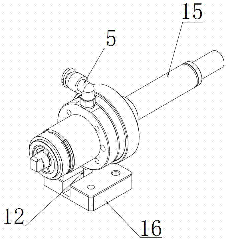
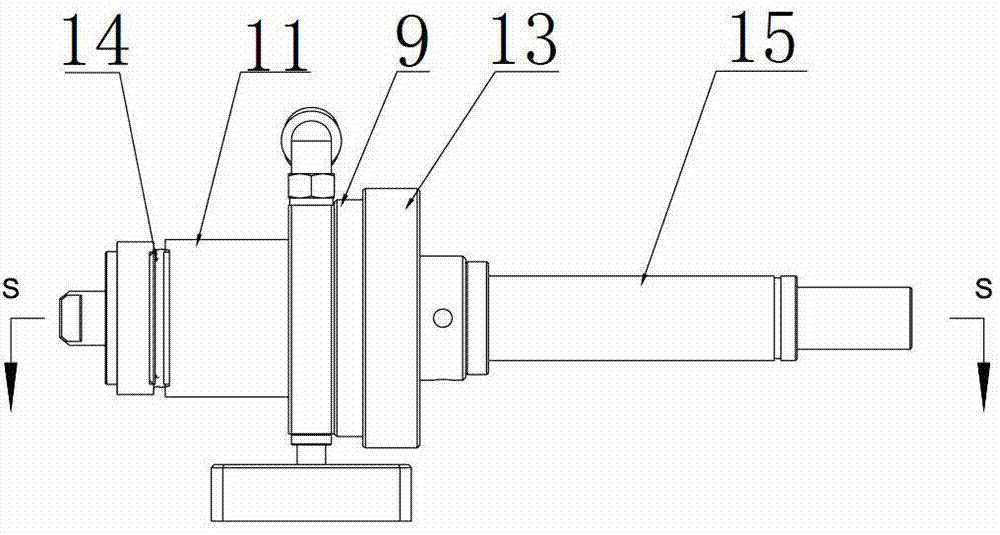
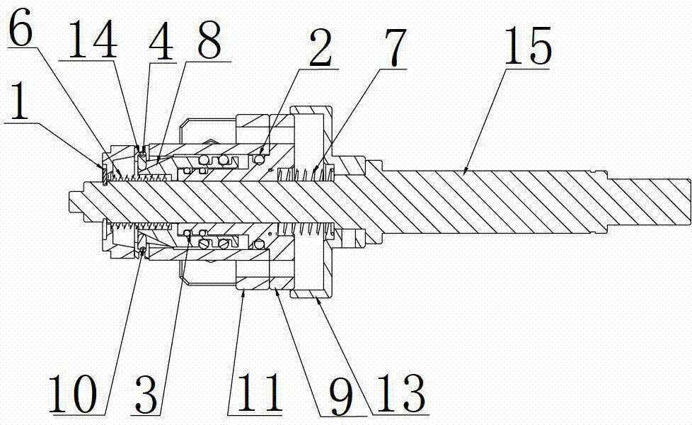
[0012] A kind of pneumatic expansion locking mechanism provided by the present invention, refer to figure 1 , figure 2 and image 3 , which includes a rotating shaft 15, an outer shaft sleeve 11, a rear base 9, a spring protection cover 13, a wedge-shaped shaft sleeve 8, a spherical pin 10, a shrapnel 14, and a guide plate 16; the rear base 9, the outer shaft sleeve 11 are installed on the rotating shaft 15 And the spring protection cover 13, the rear base 9 is located between the outer shaft sleeve 11 and the spring protection cover 13; the rear base 9 and the outer shaft sleeve 11 are fixedly sealed and connected by the sealing ring 12, and a spring protection cover 13 and the rotating shaft 15 are provided with Spring one 7; Spring two 6 is arranged between the rear base...


PUM


Abstract

The invention discloses a pneumatic expanding and clasping mechanism which comprises a rotary shaft, an outer shaft sleeve, a rear base, a spring protection cover, a wedged shaft sleeve, a spherical pin, a resilient sheet and a guide plate, wherein the rotary shaft is provided with the rear base, the outer shaft sleeve and the spring protection cover; the rear base is fixedly connected with the outer shaft sleeve in a sealed manner; a spring I is arranged between the spring protection cover and the rotary shaft; a spring II is arranged among the rear base, the outer shaft sleeve and the rotary shaft; a clamping spring is arranged on the front end face of the rotary shaft; the clamping spring is connected with the outer shaft sleeve; the wedged shaft sleeve is arranged between the rotary shaft and the outer shaft sleeve; the wedged shaft sleeve is slidingly connected with the outer shaft sleeve in the sealed manner and is connected with the rear base in the sealed manner; the spherical pin is fixedly arranged in a clamping groove of the wedged shaft sleeve; the spherical pin is connected with the resilient sheet; a fast-inserting connector is arranged at the top of the rear base and a guide pin is arranged on the bottom face; and one end of the guide pin is arranged in the guide plate. The pneumatic expanding and clasping mechanism can really simulate the work state of an automobile lock and provides good support for measuring various technical indexes of the lock.

Description

technical field [0001] The invention relates to a clasping mechanism, in particular to a pneumatic expansion clasping mechanism. Background technique [0002] With the improvement of people's living standards, people not only have more and more demand for cars, but also have higher and higher performance requirements for cars. The car lock is one of the main components to evaluate the reliability of the car. In order to meet people's needs, when manufacturing a car, it is usually necessary to rely on the testing mechanism to simulate the rotation of the lock cylinder to different positions after the key is inserted, so as to measure the internal components of the car lock through the torque sensor, pressure sensor and displacement sensor outside the car lock Various data. However, due to factors such as friction and elastic force, the existing testing institutions cannot truly simulate the working state of the car lock, so the support provided for measuring various technic...

Claims


Application Information

Patent Timeline
Patent Type & Authority Patents(China)
IPC IPC(8): E05B51/02E05B65/00
Inventor 仇荣平李寰宇
Owner RULAMATE AUTOMATIC TECHN SUZHOU
Why Eureka
Eureka Blog
Learn More