
High-pressure pneumatic blasting pressure relieving and transmission increasing method

A technology of blasting pressure relief and high-pressure gas, which is applied in earthwork drilling, gas discharge, and mining fluids. It can solve problems such as potential safety hazards, complex processes, and large water volumes, and achieve improved gas extraction rates and low permeability. easy-to-achieve effects

Active Publication Date: 2014-05-14
CHINA UNIV OF MINING & TECH
View PDF2 Cites 2 Cited by
  • Summary
  • Abstract
  • Description
  • Claims
  • Application Information

AI Technical Summary

Problems solved by technology

Exploitation of protective seams has been proven to be an effective method, but it has strict requirements on the occurrence conditions of coal seams, and not all coal seams can be applied to this method; the effect of directional hydraulic fracturing is also very significant, and the experience of the former Soviet Union shows that : It can make the gas extraction rate reach about 60%, but there will be a stress concentration area around the fracturing fracture, forming a potential safety hazard. In addition, this method has higher requirements on the sealing of the borehole, and directional hydraulic fracturing is carried out underground During the work, the high-pressure water injected into the coal body frequently flows out from the upper part of the orifice; while the hydraulic punching is suitable for soft parts with self-spraying ability, such as large ground stress, high gas pressure, soft coal quality and easy pulverization rheology. Layer, the effect is good, but it requires a large amount of water, the process is complicated, and it is not easy to popularize and utilize

Method used


Image

  • High-pressure pneumatic blasting pressure relieving and transmission increasing method

Examples


Embodiment Construction

[0009] The present invention will be further described below in conjunction with the embodiment in the accompanying drawings:

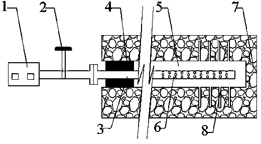
[0010] In the high-pressure pneumatic blasting pressure relief and anti-reflection method of the present invention, at first conventionally construct the blasting borehole 5 in the coal seam 7, and the depth of the blasting borehole 5 is 25-30m; The high-pressure water jet slotting operation is carried out at intervals from the inside to the outside, so that the coal body around the inside of the blasting borehole 5 forms equally spaced guiding slots 8; On the other hand, these slots and cracks can play a role in guiding and controlling, so that the high-pressure gas can concentrate and impact in several directions, the generation and penetration of cracks are better, and the blasting effect is better; The top-blocked blasting steel pipe 3 is fed into the hole 5, and a number of air holes 6 are opened on the outer wall of the front closed end of the b...


PUM


Abstract

A high-pressure pneumatic blasting pressure relieving and transmission increasing method comprises constructing a blasting drill hole in a coal layer, and carrying out high-pressure water jet seam cutting operation in the blasting drill hole at intervals, so that a lead seam groove is formed in a coal body around the blasting drill hole; feeding a blasting steel pipe with plugged top part into the blasting drill hole, forming a plurality of air vents at the front part of the blasting steel pipe, and sealing a section inside a hole opening of the blasting drill hole by 8-10 m, so as to form a cement plug; and connecting the blasting steel pipe with a high-pressure air station through a pipeline at the exposed end of the blasting steel pipe, and opening a valve arranged on the pipeline to inject high-pressure gas, so that the high-pressure gas is jetted by the blasting steel pipe from the air vents. On the basis of forming cracks and fractures formed in the fractures and cutting grooves of the original coal body, the high-pressure gas instantly impacts the blasting effect, so that the cracks and the fractures can be continuously expanded, and a lot of new fractures can be generated. Finally, a mutually communicated large fracture screen is formed in the coal body by using the blasting drill hole as a center, so that the purpose of pressure relief and transmission increase of the coal body can be realized. Furthermore, the method has the advantages of simple operation, easiness of realization and obvious effect.

Description

technical field [0001] The invention relates to a method for pressure relief and permeability enhancement of high-pressure pneumatic blasting, and is especially suitable for pressure relief and permeability enhancement of coal bodies for gas control in underground areas of coal mines. Background technique [0002] The gas geological conditions of my country's coal mines are relatively complex, among which high-gas coal seams account for 50%-70%, and low-permeability coal seams account for about 70% of them. Therefore, the prevention and control of gas should be the top priority of coal mine safety work, but for low-permeability coal seams, in order to achieve a better gas control effect, the effective realization of coal pressure relief and permeability enhancement should be the primary task . At present, there are many methods for coal pressure relief and permeability enhancement, such as mining protective layers, directional hydraulic fracturing, deep hole loosening blast...

Claims


Application Information

Patent Timeline
Patent Type & Authority Patents(China)
IPC IPC(8): E21B43/26E21F7/00
CPCE21C45/06E21F7/00E21C37/14E21B43/26
Inventor 林柏泉杨威郑春山
Owner CHINA UNIV OF MINING & TECH
Learn More