
Switching device

A technology for switching devices and switching directions, which is applied to contacts, electrical components, electric switches, etc., and can solve problems such as increased friction, potential safety hazards of switching devices, and increased contact resistance

Inactive Publication Date: 2015-04-29
SIEMENS AG
View PDF5 Cites 0 Cited by
  • Summary
  • Abstract
  • Description
  • Claims
  • Application Information

AI Technical Summary

Problems solved by technology

When the moving contact of the switching device breaks contact with the fixed contact, the moving contact may rebound towards the fixed contact, reducing the distance between the moving contact and the fixed contact. When the distance between them is smaller than the air breakdown distance, an arc that is difficult to extinguish will be generated between them, which will bring safety hazards to the use of switching devices
At the same time, the arc generated between the moving contact and the fixed contact will generate a large amount of heat, so that all the metal in the arc area will be heated and evaporate a certain amount of metal particles, and these metal particles will be partially adsorbed on the moving contact. The friction force between the moving contact and the fixed contact increases and the contact resistance becomes larger, which causes a large amount of heat to be generated between the moving contact and the fixed contact, and it is easy to burn the switching device
[0003] Existing switching devices increase the distance between the moving contact and the fixed contact by increasing the volume of the entire device. The distance between is always greater than the air breakdown distance

Method used


Image

  • Switching device
  • Switching device
  • Switching device

Examples


Embodiment Construction

[0036] In order to have a clearer understanding of the technical features, purposes and effects of the invention, the specific implementation of the present invention is now described with reference to the accompanying drawings. In the accompanying drawings representing each embodiment, the same last two digits indicate the same structure or similar structure But the function is the same, and the numerals in the hundreds place are used to represent different embodiments.

[0037] In order to make the drawing concise, the parts related to the present invention are only schematically shown in each drawing, and they do not represent the actual structure of the product. In addition, to make the drawings concise and easy to understand, in some drawings, only one of the components having the same structure or function is schematically shown, or only one of them is marked.

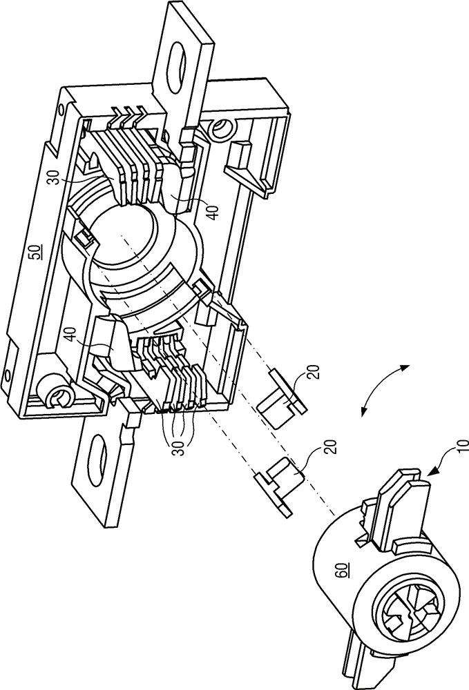
[0038] like figure 1 As shown, the switching device is provided with an outer frame 50, and the working shaft...


PUM


Abstract

The invention provides a switching device which comprises an outer frame (50), a working shaft (60), a movable contact (10), fixed contacts (40) and buffering parts (20). The working shaft, the fixed contacts and the buffering parts are all arranged in the outer frame, the movable contact is arranged on the working shaft and contacts with or breaks away from the fixed contacts to change states of the switching device, and the buffering parts can mutually rub and contact with the movable contact along a switching direction to avoid the movable contact moving towards the fixed contacts. Springback of the movable contact is limited by friction force between the buffering parts and the movable contact, so that safe distance between the movable contact and the fixed contacts can still be maintained without increasing the size of the switching device; relative friction caused when the movable contact contacts with the buffering parts can clean metal particles adhered on the contacting surface, and good contact of the movable contact and the fixed contacts can be maintained.

Description

technical field [0001] The invention relates to a switching device, in particular to a switching device using a buffer mechanism of a moving contact piece. Background technique [0002] The switching device generally includes a moving contact piece and a fixed contact piece matched with the moving contact piece, and switching between different states of the switching device is realized by contacting and disconnecting between the moving contact piece and the fixed contact piece. When the moving contact of the switching device breaks contact with the fixed contact, the moving contact may rebound towards the fixed contact, reducing the distance between the moving contact and the fixed contact. When the distance between them is smaller than the air breakdown distance, an arc that is difficult to extinguish will be generated between them, which will bring safety hazards to the use of the switching device. At the same time, the arc generated between the moving contact and the fix...

Claims


Application Information

Patent Timeline
Patent Type & Authority Patents(China)
IPC IPC(8): H01H1/50
Inventor 陈德州刘明华李大意段新高胡彦涛埃斯纳·马蒂亚斯提莫·马利希史蒂芬·塞茨亚历山大·温克勒
Owner SIEMENS AG
Learn More