All-optical microwave signal oscillator

A microwave signal and oscillator technology, applied in the field of microwave technology and optoelectronics, can solve the problems of non-adjustable light wave center frequency of photonic microwave oscillator, poor continuous tunability of microwave frequency, and low system stability.

Inactive Publication Date: 2013-02-13
GUIZHOU UNIV
View PDF2 Cites 17 Cited by
  • Summary
  • Abstract
  • Description
  • Claims
  • Application Information

AI Technical Summary

Problems solved by technology

The photonic microwave oscillator with this structure cannot adjust the center frequency of the light wave, the continuous tunability of the microwave frequency is poor, and the system stability is not high

Method used


Image

  • All-optical microwave signal oscillator
  • All-optical microwave signal oscillator
  • All-optical microwave signal oscillator

Examples


Embodiment 1

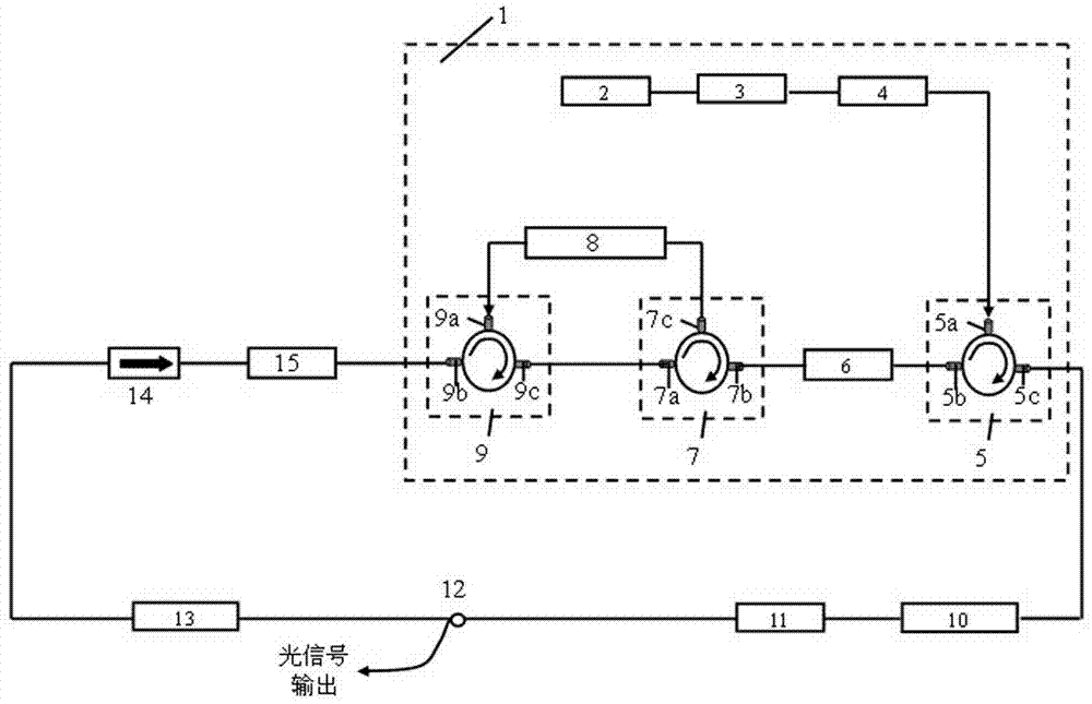
[0023] refer to figure 1, an all-optical microwave signal oscillator, including a microwave photonic filter module 1, a tunable optical bandpass filter 10, a polarization controller 11, an optical coupler 12, an optically adjustable delay line 13, an optical isolator 14, and a semiconductor optical amplifier B (SOA) 15, these components are sequentially connected through optical fibers to form a ring structure, in which the microwave photonic filter module 1 includes a broadband light source 2, a shaping optical filter 3, an adjustable comb filter 4, a three-port optical circulator A5, Semiconductor optical amplifier A (SOA) 6, three-port optical circulator B7, tunable dispersion module 8 and three-port optical circulator C9, broadband light source 2 connected to shaping optical filter 3, shaping optical filter 3 to adjustable comb The adjustable comb filter 4 is connected to the three-port optical circulator A port one 5a, the three-port optical circulator A port two 5b is co...

Embodiment 2

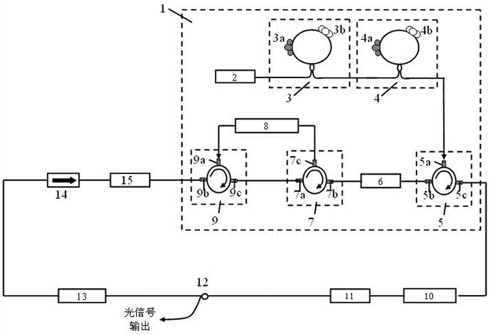
[0028] refer to figure 2 , an all-optical microwave signal oscillator, comprising a microwave photon filter module 1, a tunable optical bandpass filter 10, a polarization controller 11, an optical coupler 12, an optically adjustable delay line 13, an optical isolator 14 and a semiconductor Optical amplifier B (SOA) 15, these components are sequentially connected through optical fibers to form a ring structure, in which the microwave photon filter module 1 includes a broadband light source 2, a shaping optical filter 3, an adjustable comb filter 4, and a three-port optical circulator A5, semiconductor optical amplifier A (SOA) 6, three-port optical circulator B7, tunable dispersion module 8 and three-port optical circulator C9, broadband light source 2 is connected to shaping optical filter 3, and shaping optical filter 3 is connected to adjustable Tunable comb filter 4 connection, adjustable comb filter 4 and three-port optical circulator A port one 5a connection, three-port ...

Embodiment 3

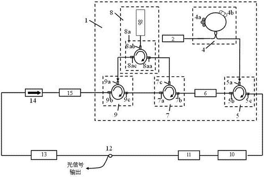
[0032] refer to image 3 , an all-optical microwave signal oscillator, including a microwave photonic filter module 1, a tunable optical bandpass filter 10, a polarization controller 11, an optical coupler 12, an optically adjustable delay line 13, an optical isolator 14, and a semiconductor optical amplifier B (SOA) 15, these components are sequentially connected through optical fibers to form a ring structure, in which the microwave photon filter module 1 includes a broadband light source 2, an adjustable comb filter 4, a three-port optical circulator A5, a semiconductor optical amplifier A (SOA ) 6. Three-port optical circulator B7, adjustable dispersion module 8 and three-port optical circulator C9, broadband light source 2 adopts superluminescent LED (SLED); adjustable comb filter 4 adopts high birefringence The optical fiber loop mirror (HB-FLM) type optical comb filter, the adjustable comb filter 4 is connected to the A port one 5a of the three-port optical circulator, ...


PUM


Abstract

The invention discloses an all-optical microwave signal oscillator which comprises a microwave photon filtration module (1), a tunable optical bandpass filter (10), a polarization controller (11), an optical coupler (12), a light adjustable delay wire (13), an optical isolator (14) and a semiconductor optical amplifier B (15). The microwave photon filtration module (1), the tunable optical bandpass filter (10), the polarization controller (11), the optical coupler (12), the light adjustable delay wire (13), the optical isolator (14) and the semiconductor optical amplifier B (15) are connected in sequence through optical fiber to form a circular structure. The microwave photon filtration module (1) comprises a broadband light source (2), a plastic optical filter (3), an adjustable comb-shaped filter (4), a three-port optical circulator A (5), a semiconductor optical amplifier A (6), a three-port optical circulator B (7), an adjustable dispersion module (8) and a three-port optical circulator C (9). The all-optical microwave signal oscillator has the advantages of being tunable in microwave frequency and light carrier frequency, high in system stability and convenient and flexible to use.

Description

technical field [0001] The invention relates to the fields of microwave technology and optoelectronic technology, in particular to an all-optical microwave signal oscillator. [0002] Background technique [0003] The all-optical microwave signal oscillator is a device that uses pure optical oscillation to generate photonic microwave signals. Its main implementation method is to use optical oscillation to generate two phase-locked optical frequencies, which can be directly transmitted in optical fibers as optical microwave subcarriers. Alternatively, the data signal can be loaded to form a light-borne wireless data signal, or an electric microwave signal can be directly generated through photoelectric conversion. This microwave signal oscillator has important applications in the fields of radio-on-fiber (ROF), broadband wireless access, radar systems, and sensor networks. [0004] There are two main types of all-optical microwave signal oscillators reported at present: ...

Claims


Application Information

Patent Timeline
Patent Type & Authority Applications(China)
IPC IPC(8): H01S1/02
Inventor 江阳白光富
Owner GUIZHOU UNIV
Why Eureka
Try Eureka