Eureka AIR delivers breakthrough ideas for toughest innovation challenges, trusted by R&D personnel around the world.

Distance measuring device and method

A distance measuring device and distance technology, applied in the field of industrial measurement, can solve the problems of not fully utilizing the laser polarization ranging system, not all using optical fiber devices, complex optical path system, etc., to achieve large-scale high-precision absolute distance measurement , Expand the operating frequency bandwidth, simplify the effect of the optical path structure

Pending Publication Date: 2021-11-16
INST OF MICROELECTRONICS CHINESE ACAD OF SCI
View PDF0 Cites 0 Cited by
  • Summary
  • Abstract
  • Description
  • Claims
  • Application Information

AI Technical Summary

Problems solved by technology

Among them, the driving voltage required by the spatial bulk phase modulator is relatively high, and the high-frequency high-voltage electrical signal is prone to cause temperature drift, which requires a complex temperature control system. The spatial collimation optical path puts forward extremely high requirements for instrument processing and assembly.
However, in order to meet the requirements for controlling the polarization state of the transmitted optical signal, the deviation ranging system using the waveguide phase modulator has problems such as not all using optical fiber devices, and the optical path system is complex, which fails to give full play to the advantages of the laser polarization ranging system.

Method used


Image

  • Distance measuring device and method
  • Distance measuring device and method
  • Distance measuring device and method

Examples


Embodiment Construction

[0045] In order to make the purpose, technical solutions and advantages of the present disclosure clearer, the present disclosure will be further described in detail below in conjunction with specific embodiments and with reference to the accompanying drawings.

[0046] It should be noted that, in the drawings or descriptions of the specification, similar or identical parts all use the same figure numbers. The technical features in the various embodiments exemplified in the specification can be freely combined to form a new solution under the premise of no conflict. In addition, each claim can be used as an embodiment alone or the technical features in each claim can be combined as a new solution. and in the drawings, the shape or thickness of the embodiments may be enlarged, and marked for simplification or convenience. Furthermore, elements or implementations not shown or described in the drawings are forms known to those of ordinary skill in the art. Additionally, while il...


PUM


Abstract

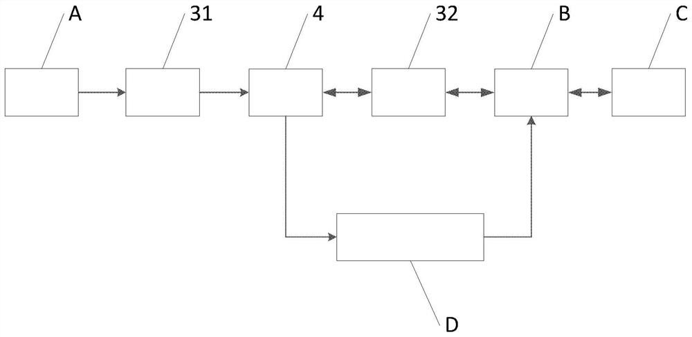
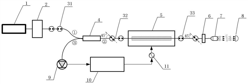
The invention provides a distance measuring device and method. The device comprises the following components of: a polarized light generation module which is used for generating linearly polarized light; a phase modulation module which is used for modulating the phase of the linearly polarized light, outputting the polarized light obtained through modulation to a measured object to generate reflected light and modulating the phase of the reflected light, wherein the reflected light is used for distance measurement; a beam splitting device which is used for carrying out polarization detection on the reflected light modulated by the phase modulation module. The phase modulation module comprises a phase modulator and a wave plate, transmission is carried out between the polarized light generation module and the beam splitting device through a first polarization-maintaining optical fiber, transmission is carried out between the beam splitting device and the phase modulator through a second polarization-maintaining optical fiber, the second polarization-maintaining optical fiber is used for controlling an included angle between polarized light and an electric field in the phase modulator to be a first angle, and transmission is carried out between the phase modulator and the wave plate through a third polarization-maintaining optical fiber, the included angle between the fast axis of the third polarization-maintaining optical fiber and the fast axis of the wave plate is a second angle, and the first angle and the second angle are equal or complementary.

Description

technical field [0001] The disclosure relates to the technical field of industrial measurement, in particular to a distance measuring device and method. Background technique [0002] Large-scale industrial measurement ranges from a few meters to tens of meters. High-precision absolute distance measurement is the technical basis of various measurement equipment used in large-scale industrial measurement. [0003] In the existing devices and methods based on laser polarization modulation ranging, a spatial volume phase modulator and a waveguide phase modulator are mostly used, both of which are systems based on a spatial optical path. Among them, the driving voltage required by the spatial bulk phase modulator is relatively high, and the high-frequency high-voltage electrical signal heat is likely to cause temperature drift, requiring a complex temperature control system, and the spatial collimation optical path puts forward extremely high requirements for instrument processin...

Claims


Application Information

Patent Timeline
Patent Type & Authority Applications(China)
IPC IPC(8): G01S17/48
CPCG01S17/48
Inventor 高超纪荣祎董登峰周维虎石俊凯潘映伶
Owner INST OF MICROELECTRONICS CHINESE ACAD OF SCI
Why Eureka
Eureka Blog
Learn More