Check patentability & draft patents in minutes with Patsnap Eureka AI!

Cotton sampling device

A sampling equipment, cotton technology, applied in the direction of sampling devices, etc., can solve the problems of inability to adjust, sampling parts that cannot be used, and cannot be rotated

Inactive Publication Date: 2013-02-27
上海出入境检验检疫局工业品与原材料检测技术中心
View PDF7 Cites 0 Cited by
  • Summary
  • Abstract
  • Description
  • Claims
  • Application Information

AI Technical Summary

Problems solved by technology

[0006] The shortcomings and defects of the above two types: both can only obtain cotton samples on the surface of the cotton bale; it needs to be manually cut horizontally with a knife, and then the cotton samples are taken out manually, which cannot achieve automatic sampling; the depth of sampling is limited by the width of the blade, can not be adjusted
[0007] The existing cotton sampling heads with vertical parallel double-knife structure knives all use thin blades. These blades can only be inserted into the cotton bale vertically in one direction, and cannot perform cutting actions such as rotation.
In addition, when the blade of the prior art is inserted into the cotton bale, because the blade has a very small edge angle and both sides are attached to the cotton, the resistance is very large, and deep sampling cannot be realized.
[0008] The circular cutting type sampling of cotton bale still does not have relevant bibliographical record at present, is applicable to the cotton sampling head with circular cutting type sampling knife and cotton sample pawl that is suitable for circular cutting type sampling especially has no way of reporting, the sampling of prior art Sampling components in the device simply cannot be used in this situation
In addition, the sampling equipment in the prior art does not have a device with a cotton bale steering function and a cotton bale weighing function, so that the cotton bale weight inspection and cotton sampling work cannot be completed at the same time

Method used


Image

  • Cotton sampling device
  • Cotton sampling device
  • Cotton sampling device

Examples


Embodiment Construction

[0070] The present invention will be further described below in combination with specific embodiments. It should be understood that these examples are only used to illustrate the present invention and are not intended to limit the scope of the present invention. In addition, it should be understood that after reading the teachings of the present invention, those skilled in the art can make various changes or modifications to the present invention, and these equivalent forms also fall within the scope defined by the appended claims of the present application.

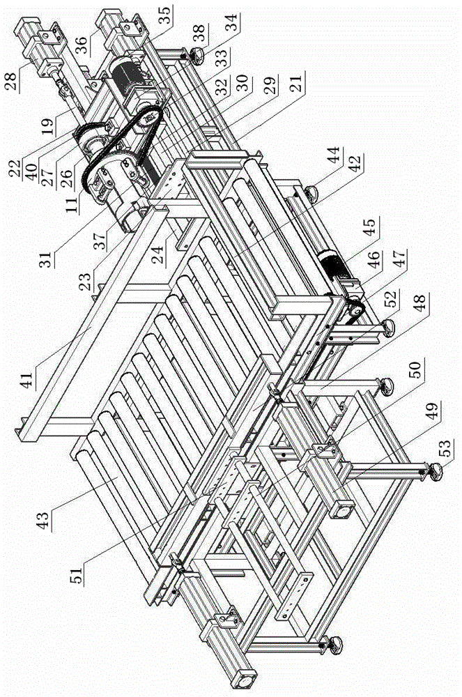
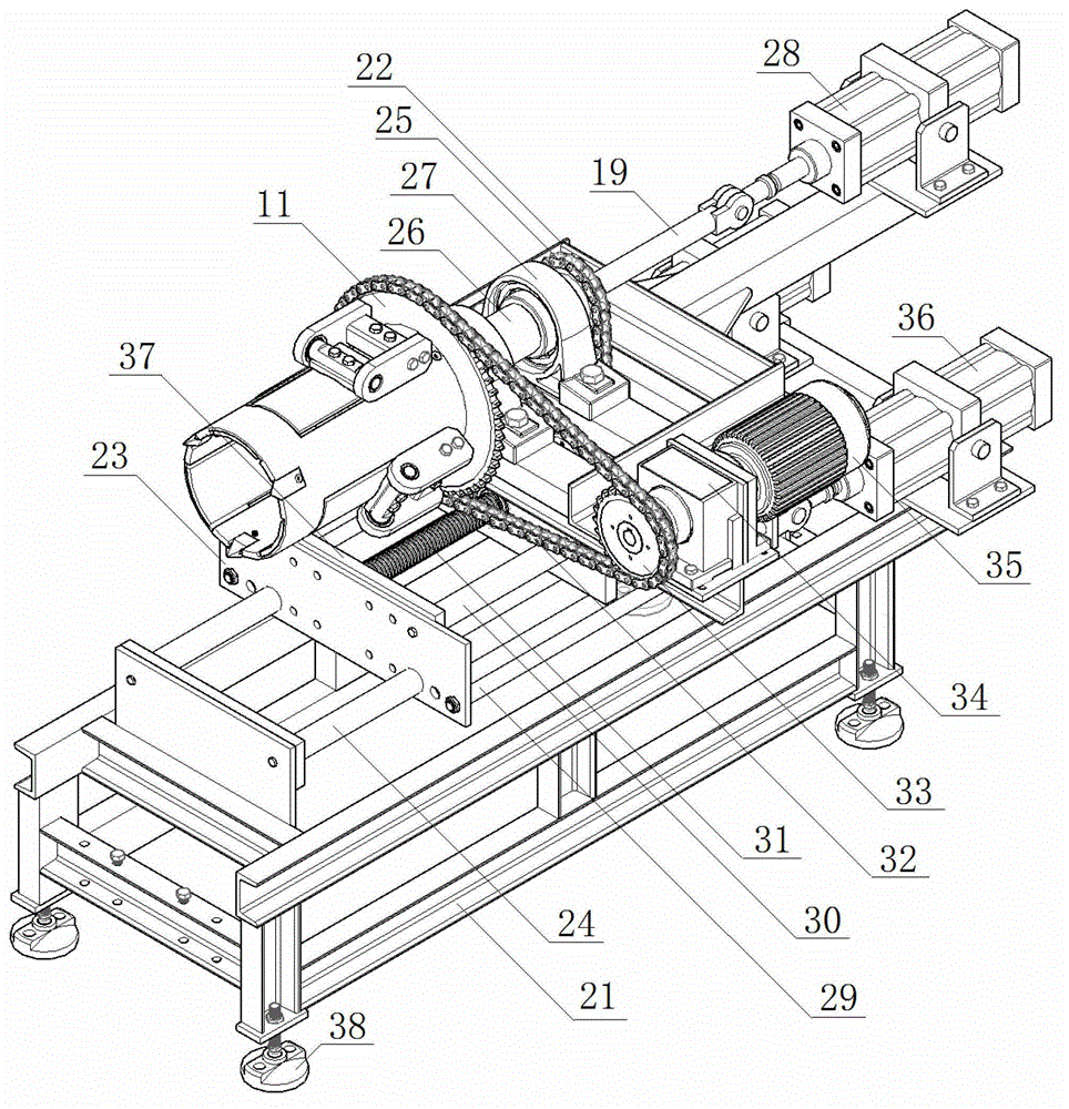
[0071] Such as figure 1 and 2 Shown, is a kind of cotton sampling equipment of the present invention, described cotton sampling equipment comprises mechanical execution device and PLC electrical control system; Ⅳ), cotton bale in-situ steering conveyor (Ⅴ), dynamic weighing device (Ⅵ) and transmission raceway (Ⅶ);

[0072] Cotton bales turn to the conveyor (Ⅴ) on the spot and connect the dynamic weighing device (Ⅵ) an...


PUM

PropertyMeasurementUnit
angleaaaaaaaaaa

Abstract

The invention relates to a cotton sampling device, particularly to a cotton sampling device provided with a round cutting type sampling cutter and a cotton sample claw. The sampling device is composed of a mechanical executive device and a programmable logic controller (PLC) electric control system, wherein the mechanical executive device is composed of a cotton sampling unit, a cotton bale conveying clamping unit, a cotton bale on-site steering conveyor, a dynamic weighing unit and a conveying raceway; the cotton bale on-site steering conveyor is connected with the dynamic weighing unit and the conveying raceway in front and the cotton conveying clamping unit and the cotton sampling unit on the side sequentially. Round cutting type sampling can be achieved through the cotton sampling cutter, the cotton sample claw can grab cotton samples out after the cotton sample cutting and then release the cotton samples, namely, feeding forward and round cutting are performed simultaneously, the obtained cotton samples are in cake shapes, and the sampling depth can be adjusted freely as required.

Description

technical field [0001] The invention relates to a cotton sampling device, in particular to a cotton sampling device with a circular cutting type sampling knife and cotton sample claws. Background technique [0002] At present, cotton bale sampling in the world is mainly manual sampling and mechanical sampling, and mechanical sampling is mainly based on the hydraulic cotton cutting machine developed in the United States, but this method belongs to semi-automatic sampling. [0003] The sampling parts of the hydraulic cotton cutting machine developed in the United States are located on both sides of the cotton bale raceway. It adopts a vertical parallel double-knife structure with a distance of 150 mm. When sampling, the hydraulic valve controls the double knives to cut in from both sides of the bale body. In the cotton bale, two large openings of about 254 mm in length were cut on both sides of the cotton bale from top to bottom, and then cut horizontally with a knife manually...

Claims


Application Information

Patent Timeline
Patent Type & Authority Applications(China)
IPC IPC(8): G01N1/04
Inventor 赵洁陆维民何秀玲周之平袁志磊
Owner 上海出入境检验检疫局工业品与原材料检测技术中心
Features
  • R&D
  • Intellectual Property
  • Life Sciences
  • Materials
  • Tech Scout
  • Unparalleled Data Quality
  • Higher Quality Content
  • 60% Fewer Hallucinations
Learn More