Ejection mechanism and electric connector utilizing same

A technology of electrical connectors and driving mechanisms, which is applied in the direction of connection and connection of parts and circuits of devices, and can solve the problems that electrical connectors cannot be separated quickly

Inactive Publication Date: 2013-03-06
CHINA AVIATION OPTICAL-ELECTRICAL TECH CO LTD
View PDF7 Cites 9 Cited by
  • Summary
  • Abstract
  • Description
  • Claims
  • Application Information

AI Technical Summary

Problems solved by technology

[0003] The purpose of the present invention is to provide an ejection mechanism to solve the problem that the existing electrical connectors cannot be separated quickly

Method used


Image

  • Ejection mechanism and electric connector utilizing same
  • Ejection mechanism and electric connector utilizing same
  • Ejection mechanism and electric connector utilizing same

Examples


Embodiment Construction

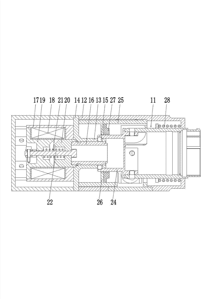
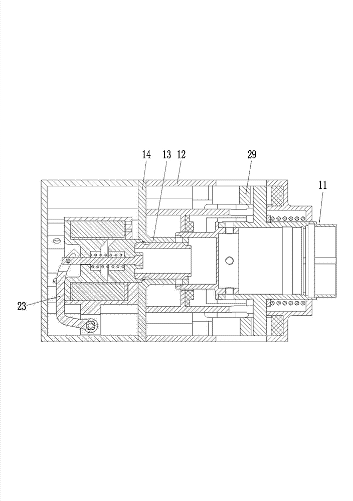
[0020] Embodiment 1 of the electrical connector of the present invention, such as Figure 1-2 As shown, it includes an electrical connector body 11 and an ejection mechanism. The ejection mechanism includes a housing 12. The housing 12 is a split structure and includes a front half and a rear half connected by screws. The housing 12 has a mounting channel extending in the front-to-rear direction, and the mounting channel is provided with a front-to-rear direction extending The fixing sleeve 13 has a mounting plate 14 formed at the rear of the fixing sleeve 13 diverging and extending radially outwards. The mounting plate 14 is fixed between the front half and the back half of the housing 12, and the fixing sleeve 13 passes through the mounting plate. 14 is fixed in the installation channel of the shell; in addition, the front wall of the fixing sleeve 13 is provided with a steel ball hole which is transparent inside and outside, and a steel ball 15 is assembled in the steel ball...


PUM


Abstract

The invention relates to the field of an electric connector, in particular to an ejection mechanism and an electric connector utilizing same. The ejection mechanism comprises a shell and a fixed sleeve, wherein a steel ball is assembled on the wall of the fixed sleeve, a lock core is assembled inside the fixed sleeve, the lock core is in transmission connection with a drive mechanism, the front end of the lock core is provided with a reducing section with reduced outer diameter, the rear part of the lock core pushes against a pushing spring, the front part of the fixed sleeve is provided with a locking sleeve, the rear end of the locking sleeve is provided with an enlarging section with increased inner diameter, the front end of the shell is provided with an inner flange, a cavity for storing the corresponding electric connector is formed between the locking sleeve and the inner flange inside an installation passage, a separation spring which is matched with the inner flange on the front end of the shell to push backwards the locking sleeve is arranged inside the cavity, and the front end of the locking sleeve is provided with a connection part which is fixedly connected with the corresponding electric connector; and the separation between the electric connector utilizing the ejection mechanism and a matched electric connector is realized through the separation spring, so that the problem that the existing electric connector cannot be rapidly separated can be solved.

Description

Technical field [0001] The invention relates to the field of electrical connectors, in particular to an ejection mechanism and an electrical connector using the ejection mechanism. Background technique [0002] Electrical connectors (plugs or sockets), as accessories for connecting circuits, have gradually become more and more widely used in communication, control and other fields with their fast and convenient characteristics. In most cases, the insertion and separation of electrical connectors are operated by humans, but there are also occasions where electrical connectors can be inserted manually and have the function of rapid separation or automatic separation. However, the current electrical connectors None of the above requirements can be met. Summary of the invention [0003] The purpose of the present invention is to provide an ejection mechanism to solve the problem that the existing electrical connector cannot be separated quickly. [0004] At the same time, the object o...

Claims


Application Information

Patent Timeline
Patent Type & Authority Applications(China)
IPC IPC(8): H01R13/635H01R13/46
Inventor 卞书波陈继利
Owner CHINA AVIATION OPTICAL-ELECTRICAL TECH CO LTD
Why Eureka
Try Eureka