
Air pressure slide mechanism

A travel position and air pressure technology, applied in the field of air pressure travel position mechanism, can solve the problems of broken travel position, poor control of travel position classification and reset sequence, etc.

Inactive Publication Date: 2013-03-13
DALIAN GAOHONG PRECISION MOLD
View PDF0 Cites 0 Cited by
  • Summary
  • Abstract
  • Description
  • Claims
  • Application Information

AI Technical Summary

Problems solved by technology

[0002] In the existing hydraulic positioning mechanism, the classification and reset sequence of the positioning is often not well controlled, resulting in damage to the positioning, and when the positioning mechanism is closing the mold, the ejection mechanism will occur. Interference is now, so it is urgent to design a travel mechanism that can overcome the deficiencies in the current technology

Method used


Image

  • Air pressure slide mechanism

Examples


Embodiment Construction

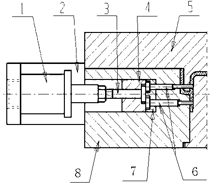
[0010] Such as figure 1 As shown, the pneumatic positioning mechanism includes an oil cylinder 1, a bracket 2, a pull rod 3, a positioning position 4, a front mold 5, a positioning needle 6, a fixed plate 7 and a rear mold 8, and the positioning position 4 is set on the front mold 5 and the rear mold 8, the bracket 2 is installed on the end faces of the front mold 5 and the rear mold 8, the oil cylinder 1 is installed on the bracket 2 and connected to the row position 4 through the pull rod 3, and the row position needle 6 is connected to the row position 4 through the fixed plate 7 , because the positioning needle 6 passes through the front mold, the positioning needle must be pulled out before the mold is opened, and the positioning mechanism can be reset after the mold is closed, and the positioning is locked by the pressure of the oil cylinder. The agency interfered.


PUM


Abstract

The invention discloses an air pressure slide mechanism which comprises an oil cylinder (1), a support (2), a pull bar (3), a slide (4), a front mold (5), a slide needle (6), a fixed plate (7), and a back mold (8); the slide (4) is disposed between the front mold (5) and the back mold (6); the support (2) is mounted on end faces of the front mold (5) and the back mold (6); the oil cylinder (1) is mounted on the support (2) and is connected with the slide (4) through the pull bar (3); the slide needle (6) is connected with the slide (4) through the fixed plate (7). The air pressure slide mechanism of the invention realizes lateral parting or core pulling by using air pressure and through an oil cylinder (air cylinder) piston and a control system; a hydraulic slide mechanism has the characteristics of long slide stroke, large parting power, no limitation to parting and core pulling by mold opening time and ejection time, and steady and flexible motion.

Description

technical field [0001] The invention relates to a pneumatic displacement mechanism. Background technique [0002] In the hydraulic position mechanism in the prior art, the classification and reset sequence of the position is often not well controlled, resulting in the phenomenon of damage to the position, and when the position mechanism is closed, the ejection mechanism will occur. Interference is now, so it is urgent to design a travel mechanism that can overcome the deficiencies in the present technology. Contents of the invention [0003] The object of the present invention is to provide a pneumatic displacement mechanism. [0004] The technical scheme adopted by the present invention to achieve the above purpose is: a pneumatic positioning mechanism, including an oil cylinder (1), a bracket (2), a pull rod (3), a positioning position (4), a front mold (5), a positioning position Needle (6), fixed plate (7) and rear mold (8), the row position (4) is set between the fr...

Claims


Application Information

Patent Timeline
IPC IPC(8): B29C33/44
Inventor 车向前
Owner DALIAN GAOHONG PRECISION MOLD
Learn More