Hydraulic slide mechanism

A displacement and hydraulic technology, which is applied in the field of hydraulic displacement mechanism, can solve the problems of poor control of displacement classification and reset sequence, damage of displacement, etc.

Inactive Publication Date: 2013-03-13
DALIAN GAOHONG PRECISION MOLD
View PDF0 Cites 3 Cited by
  • Summary
  • Abstract
  • Description
  • Claims
  • Application Information

AI Technical Summary

Problems solved by technology

[0002] In the existing hydraulic positioning mechanism, the classification and reset sequence of the positioning is often not well controlled, resulting in damage to the positioning, and when the posi

Method used


Image

  • Hydraulic slide mechanism

Examples


Embodiment Construction

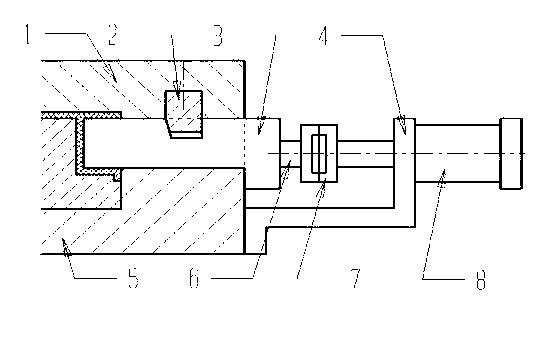
[0010] Such as figure 1 As shown, the hydraulic displacement mechanism includes front mold 1, locking block 2, row position 3, bracket 4, rear mold 5, pull rod 6, connector 7 and oil cylinder 8, and row position 3 is set on front mold 1 and rear mold 5, the front mold 1 is fixed on the row position 3 through the locking block 2, the tie rod 6 is connected to the row position 3, the connector 7 is arranged on the tie rod 6, and the oil cylinder 8 is fixedly connected to the tie rod 6 through the bracket 4. Position mechanism When the locking block 2 leaves the position, the position mechanism can be separated. Before the mold is closed, the position mechanism must be reset first. After the mold is closed, the locking block 2 locks the position. When the position mechanism and the ejector When the projections of the mechanisms in the mold opening direction overlap, the first reset mechanism should be considered to allow the ejector mechanism to reset first. When the inclined gui...


PUM


Abstract

The invention discloses a hydraulic slide mechanism, which includes a female mold (1), a locking block (2), a slide (3), a bracket (4), a male mold (5), a pull rod (6), a connector (7) and an oil cylinder (8). The slide (3) is disposed between the female mold (1) and the male mold (5). The female mold (1) is fixed on the slide (3) through the locking block (2). The pull rod (6) is connected to the slide (3). The connector (7) is arranged on the pull rod (6), and the oil cylinder (8) is in fixed connection with the pull rod (6) through the bracket (4). The hydraulic slide mechanism provided in the invention makes use of the pressure of a liquid or gas to realize side parting or core pulling through an oil cylinder (air cylinder) piston. The hydraulic slide mechanism has the characteristics of long slide stroke, great parting force, parting and core pulling free of mold opening time and ejection time limit, as well as smooth and flexible motion.

Description

technical field [0001] The invention relates to a hydraulic displacement mechanism. Background technique [0002] In the hydraulic position mechanism in the prior art, the classification and reset sequence of the position is often not well controlled, resulting in the phenomenon of damage to the position, and when the position mechanism is closed, the ejection mechanism will occur. Interference is now, so it is urgent to design a travel mechanism that can overcome the deficiencies in the present technology. Contents of the invention [0003] The purpose of the present invention is to provide a hydraulic displacement mechanism. [0004] The technical solution adopted by the present invention to achieve the above purpose is: a hydraulic displacement mechanism, including a front mold (1), a locking block (2), a displacement position (3), a bracket (4), and a rear mold (5) , pull rod (6), connector (7) and oil cylinder (8), the row position (3) is set between the front mold ...

Claims


Application Information

Patent Timeline
IPC IPC(8): B29C33/46
Inventor 车向前
Owner DALIAN GAOHONG PRECISION MOLD
Why Eureka
Try Eureka