Packaging structure for ultraviolet luminous diode

A light-emitting diode and packaging structure technology, which is applied in the direction of electrical components, electrical solid devices, circuits, etc., can solve the problems of not being able to adapt to harsh application environments, poor stability, and poor airtightness, so as to avoid device aging, good airtightness, and Strong anti-interference ability

Inactive Publication Date: 2013-03-20
QINGDAO JASON ELECTRIC
View PDF3 Cites 14 Cited by
  • Summary
  • Abstract
  • Description
  • Claims
  • Application Information

AI Technical Summary

Problems solved by technology

[0008] The purpose of the present invention is to provide a firm and practical packaging structure of ultraviolet light-emitting diodes to solve

Method used


Image

  • Packaging structure for ultraviolet luminous diode
  • Packaging structure for ultraviolet luminous diode
  • Packaging structure for ultraviolet luminous diode

Examples


Embodiment 1

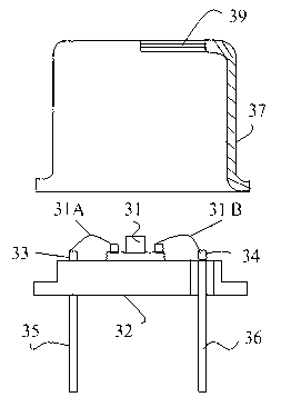
[0030] Embodiment 1. In order to improve the airtightness of the ultraviolet light-emitting diode package and the ability to resist various harsh environments, this embodiment proposes a new packaging structure for the light-emitting chip 31 that emits ultraviolet light. See image 3 As shown, it includes a TO type metal socket 32 ​​and a metal cap 37. At least two pins are provided on the metal tube base 32 , respectively defined as positive pins 35 and negative pins 36 , which are respectively connected to the tube base electrodes 33 and 34 correspondingly. The socket electrodes 33, 34 are respectively connected to the positive and negative electrodes of the light-emitting chip 31 through a wire 31A, 31B (preferably gold wire), so that the positive and negative electrodes of the light-emitting chip 31 pass through the pins of the metal socket 32. 35 and 36 lead out to realize the indirect connection between the light-emitting chip 31 and the external power supply, and contro...


PUM


Abstract

The invention discloses a packaging structure for an ultraviolet luminous diode. The packaging structure for the ultraviolet luminous diode comprises a TO type metal pipe seat with a plurality of pipe feet and a metal pipe cap, wherein a luminous chip emitting ultraviolet light is arranged on the metal pipe seat, and a positive electrode and a negative electrode of the luminous chip are respectively welded on a positive electrode pipe foot and a negative electrode pipe foot of the metal pipe seat through wires. The metal pipe cap is fixed on the metal pipe seat, a light-transmitting window body is arranged on the metal pipe cap, and the light-transmitting rate is greater than 50 percent at an ultraviolet band. The packaging structure for the ultraviolet luminous diode is stable and, strong in anti-interference capacity, and has the advantages of being good in air tightness, firm in structure and the like. Good protection, anti-oxidation and water-proof functions for the ultraviolet luminous chip can be achieved, and therefore normal use of ultraviolet light sources utilizing the packaging structure in any environmental condition is practically ensured, the problem of aging of devices due to packaging materials is avoided, and service life of the ultraviolet luminous diode is prolonged.

Description

technical field [0001] The invention belongs to the technical field of packaging technology of solid-state semiconductor light-emitting devices, and in particular relates to a packaging structure of ultraviolet light-emitting diodes. Background technique [0002] For ultraviolet light source products, the light-emitting wavelength is generally between 200nm and 350nm. These short-wavelength light-emitting light sources can be used in the fields of air or water purification, skin disease treatment, biological detection, and military communications. Moreover, the application environment of ultraviolet light source devices in this band is relatively complicated, and it may need to work underwater, or work in harsh weather or even high and low pressure conditions, so the packaging requirements for ultraviolet light source devices in this band are also very special , it must be able to ensure that the ultraviolet light source will not be disturbed by the external environment unde...

Claims


Application Information

Patent Timeline
IPC IPC(8): H01L33/48H01L33/56H01L33/52
CPCH01L2224/48091H01L2224/48247H01L2224/8592H01L2924/181H01L2924/00014H01L2924/00012
Inventor 武帅
Owner QINGDAO JASON ELECTRIC
Why Eureka
Try Eureka