
heat exchange equipment

一种热交换设备、热传递的技术,应用在热交换设备、蓄热设备、照明和加热设备等方向,能够解决热交换器贮热能力不足等问题

Active Publication Date: 2016-03-16
ABB (SCHWEIZ) AG
View PDF6 Cites 0 Cited by
  • Summary
  • Abstract
  • Description
  • Claims
  • Application Information

AI Technical Summary

Problems solved by technology

[0003] The problem with the heat exchangers described above is that they have insufficient heat storage capacity, especially when dealing with temporary peaks in the amount of heat generated by electrical components

Method used


Image

  • heat exchange equipment
  • heat exchange equipment
  • heat exchange equipment

Examples


Embodiment Construction

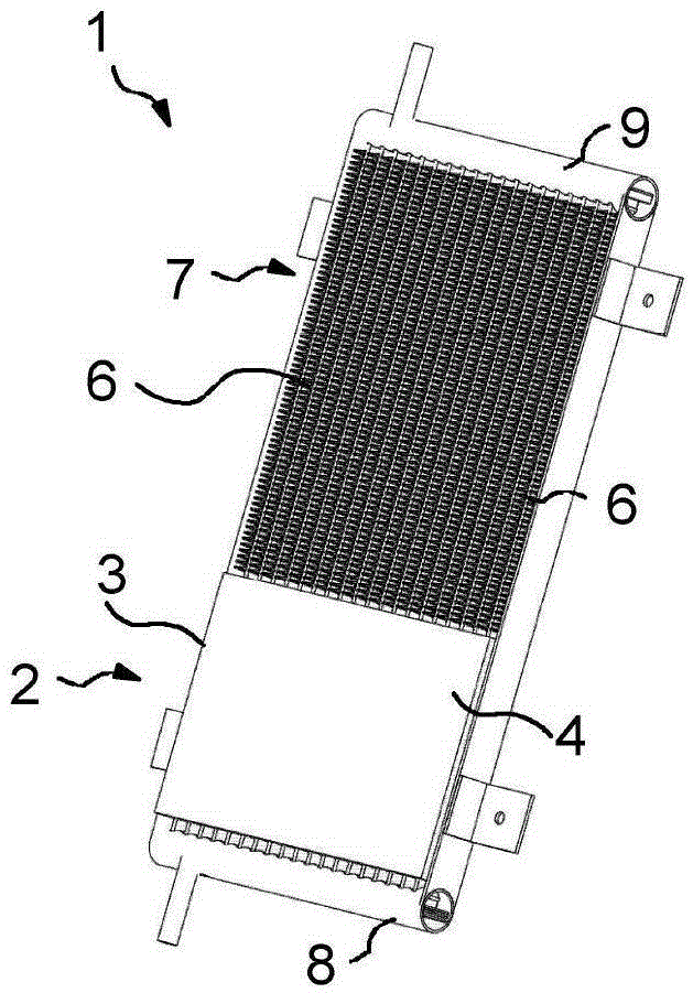
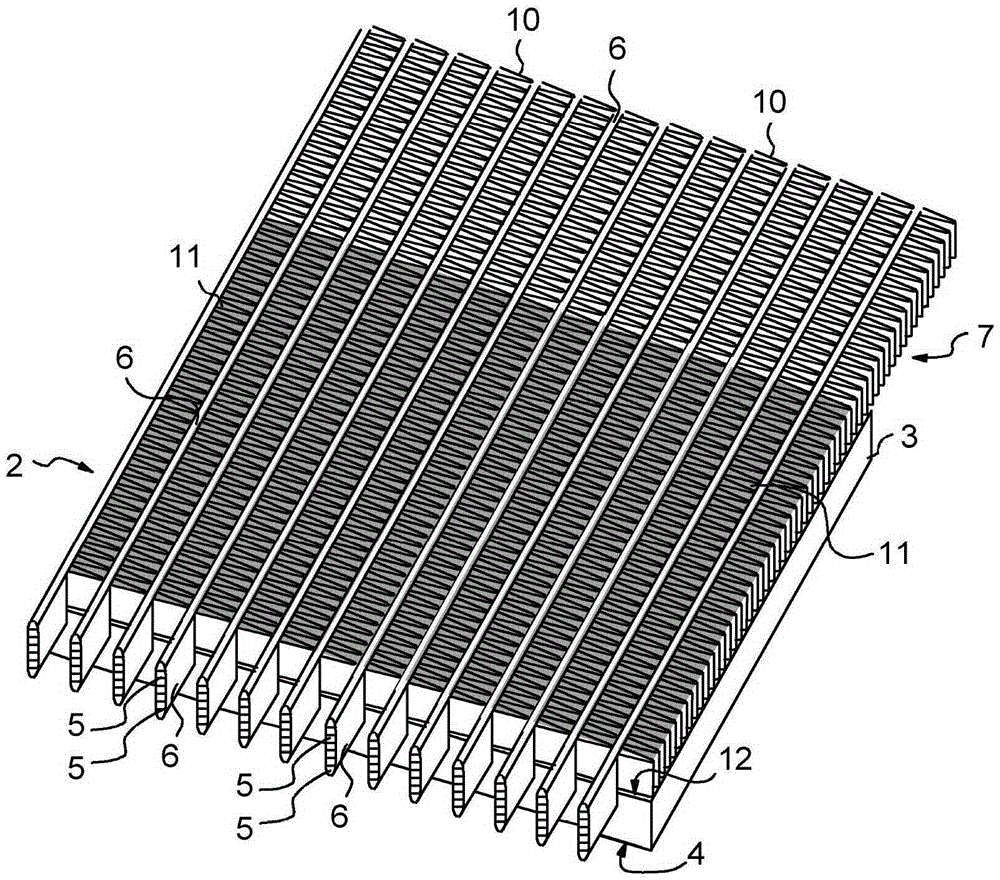
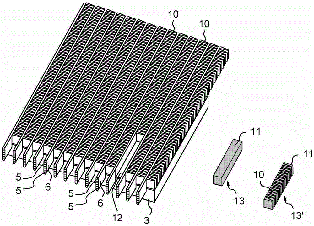
[0013] Figures 1 to 2 A first embodiment of the device 1 is depicted. The device comprises a first heat transfer element 2 comprising a base plate 3 having a first surface 4 for receiving one or more electrical components which require cooling during their use to avoid temperatures overly elevated. The first heat transfer element 2 also comprises a plurality of channels 5 for transferring the received heat load into a fluid circulating in said channels. From figure 2 As can be seen in the figure, in this embodiment the channels 5 are arranged in a duct 6 which is spaced apart and has an inner wall separating the plurality of channels 5 from each other. The pipe may be an MPE (Multiple Extruded) pipe, made eg by extruding aluminium. exist figure 1 In , the device 1 is observed along the direction that the substrate 3 is at the top of the pipe 6, while figure 2 Only some parts of the device 1 are depicted in the direction in which the pipe 6 is located on top of the bas...


PUM


Abstract

The invention relates to a heat exchange device (1) comprising: a first heat transfer element (2) comprising a base plate (3) and a channel (5), the base plate (3) having a first surface (4) for receiving electrical components (16), said channel (5) for transferring a thermal load received via said first surface (4) to a fluid in said channel (5) wherein at least some of said channels (5) protrude from a second surface (12) of said substrate (3); and a second heat transfer element for receiving fluid from said first heat transfer element and transferring The heat load from the fluid is delivered to the surroundings. In order to obtain efficient cooling, a phase change material (11) is arranged on the second surface (12) of the substrate (3), between at least two channels (5), during operation of the electrical component, all The phase-change material (11) absorbs heat by undergoing a phase-change at a phase-change temperature.

Description

technical field [0001] The invention relates to a heat exchange device, in particular to a heat exchange device for cooling electric components. Background technique [0002] Devices with heat exchangers having a first heat transfer element comprising a base plate for electrical components and having channels for conveying heat loads from the base plate to the channels are known before in the fluid. The fluid is conveyed via channels to a second heat exchanger in which the fluid is cooled. At least some of the channels protrude from the surface of the substrate. [0003] A problem with the heat exchangers described above is that they have insufficient heat storage capacity, especially when dealing with temporary peaks in the amount of heat generated by electrical components. Contents of the invention [0004] The object of the present invention is to provide a heat exchange device which solves the above mentioned disadvantages. [0005] By using phase change materials ...

Claims


Application Information

Patent Timeline
Patent Type & Authority Patents(China)
IPC IPC(8): H05K7/20
CPCH05K7/20936H05K7/20945F28D20/02F28D15/0275F28D15/0266F28D2020/0013F28F27/00Y02E60/14F28F9/00
Inventor 布鲁诺·阿戈斯蒂尼马蒂厄·哈贝特马蒂·考拉宁马尔库·埃洛
Owner ABB (SCHWEIZ) AG
Features
  • Generate Ideas
  • Intellectual Property
  • Life Sciences
  • Materials
  • Tech Scout
  • Unparalleled Data Quality
  • Higher Quality Content
  • 60% Fewer Hallucinations
Learn More