Novel axial-flow fan with small-aspect-ratio blades having obliquely-cut and twisted blade roots

An axial flow fan, twisted blade technology, applied in mechanical equipment, machines/engines, liquid fuel engines, etc., can solve problems such as high outlet wind pressure, achieve high supercharging capacity, high bending rigidity, and achieve wind pressure requirements and the effect of efficiency

Active Publication Date: 2015-06-17
DALIAN UNIV OF TECH
View PDF9 Cites 0 Cited by
  • Summary
  • Abstract
  • Description
  • Claims
  • Application Information

AI Technical Summary

Problems solved by technology

[0003] Due to the change of the operating environment, the original fan can no longer meet the new operating conditions. Therefore, it is required to maintain a high outlet air pressure and a good fan under the harsh conditions of constant external dimensions, reduced speed, reduced flow, and power not exceeding the limit. operation efficiency

Method used


Image

  • Novel axial-flow fan with small-aspect-ratio blades having obliquely-cut and twisted blade roots
  • Novel axial-flow fan with small-aspect-ratio blades having obliquely-cut and twisted blade roots
  • Novel axial-flow fan with small-aspect-ratio blades having obliquely-cut and twisted blade roots

Examples


Embodiment 1

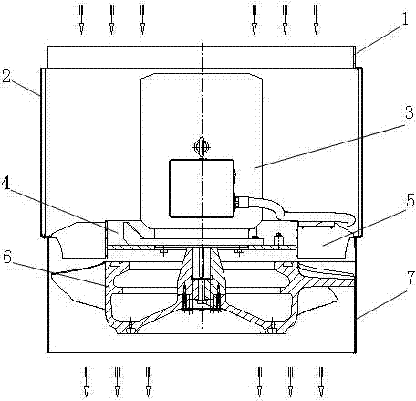
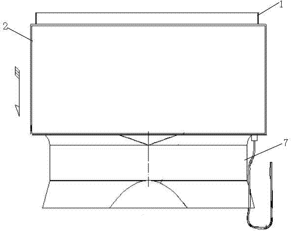
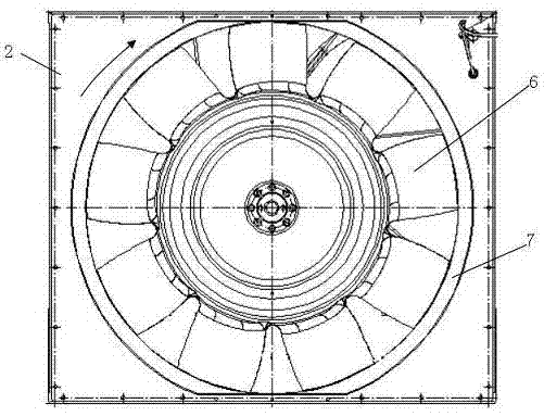
[0030] Such as figure 1 As shown in -4, the novel small-aspect-ratio blade root beveled twisted blade type axial flow fan device of the present invention consists of an air inlet interface 1, an air inlet chamber 2, a drive motor 3, a support ring 4, a support plate 5, and an impeller 6 and exhaust section 7 form. The drive motor 3 is placed on the support ring 4 in the center of the rear part of the air inlet chamber 2, and is directly connected to the impeller 6 through the shaft. The part where the wind section 7 is connected. The inlet of the air inlet chamber 2 is provided with an air inlet connection port 1, which is connected to the front air inlet. The exhaust section 7 is divided into two parts: a cylinder section and a diffuser section, which are closely connected with the air inlet chamber 2 to form the main flow part. . Eight pieces (two groups) of equal-thick support plates 5 with diversion function are welded between the air inlet chamber 2 and the air exhaust...

Embodiment 2

[0034]The basic structure is the same as that of Example 1, suitable for large-flow fans. The wheel-to-hub ratio of the impeller is 0.7. The blades adopt 9 twisted blades with variable cross-section and variable thickness. The aspect ratio is 0.7, and 8 equal-thick support plates are welded. The trailing edge of the blade root is chamfered and rounded, with a cutting angle of 15° and a rounding radius of 20mm.

Embodiment 3

[0036] The basic structure is the same as that of Example 1, which is suitable for fans with small flow rate. The hub ratio of the impeller is 0.5. The blades adopt 12 twisted blades with variable cross-section and variable thickness. The aspect ratio is 0.9, 12 equal-thick support plates are welded, the trailing edge of the blade root is chamfered and rounded, the cutting angle is 20°, and the rounding radius is 10mm.


PUM


Abstract

The invention belongs to the technical field of ventilators, and particularly relates to an axial-flow fan. A novel axial-flow fan with small-aspect-ratio blades having obliquely-cut and twisted blade roots comprises an air inlet chamber, a motor, a support ring, support plates, an impeller, an exhaust segment and the like, wherein the motor is arranged on the support ring in the center of the back part of the air inlet chamber, and is directly connected with the impeller through a shaft; the hub and blades of the impeller are designed integrally; the trailing edges of the blade roots of the blades are cut obliquely; an air inlet is formed in the air inlet end of the air inlet chamber and is connected with an air inlet channel at the front end; the exhaust segment is tightly connected with the air inlet chamber to construct a main through flow part; and the outlet segment of the exhaust segment is enlarged gradually. Due to the adoption of the novel axial-flow fan, the stability of axial air inflow of inlet air current and an inlet flow field is ensured; the fan is simple and compact in structure, and is convenient to manufacture; and under the conditions of limited size, low rotating, low flow and the like, the impeller has high boosting capability and high running efficiency.

Description

technical field [0001] The invention belongs to the technical field of fans, in particular to an axial flow fan. Background technique [0002] With the continuous improvement of high-speed and heavy-load requirements for domestic locomotives, the heat generated by locomotive power equipment has increased. In order to ensure the safe and stable operation of locomotives, the requirements for special cooling fans for cooling the heating parts of locomotives are constantly increasing. At present, most of my country adopts imported cooling fans. When the conditions of use change, imported fans have long procurement cycles, high costs, and inconvenient maintenance. It is difficult to meet the requirements of the development of domestic railway transportation. The traction motor of the EMU locomotive has the characteristics of high power and many heating electrical components. At the same time, the structure of the locomotive car, the inlet and outlet channels and the operating co...

Claims


Application Information

Patent Timeline
Patent Type & Authority Patents(China)
IPC IPC(8): F04D25/08F04D29/32F04D29/38F04D29/52F04D29/58
Inventor 王晓放杨晓清徐胜利罗艾然吴联军姜治迅薛家好
Owner DALIAN UNIV OF TECH
Why Eureka
Try Eureka