
Radiation-refrigerating ceiling structure

A radiant cooling and ceiling technology, applied in the direction of ceiling, building components, prevention of condensed water, etc., can solve problems such as the inability to effectively avoid condensation and dripping, affecting the quality of life of users, and applicable environmental restrictions, saving initial investment, Wide range of use, improved quality of life effect

Pending Publication Date: 2019-10-25
HEBEI UNIV OF TECH
View PDF1 Cites 2 Cited by
  • Summary
  • Abstract
  • Description
  • Claims
  • Application Information

AI Technical Summary

Problems solved by technology

[0003] At present, the commonly used refrigeration ceiling system needs to add a replacement ventilation system. By controlling the temperature and humidity of the incoming air, the dew point temperature is lower than the surface temperature of the ceiling to avoid condensation. Extremely limited, not only complex in structure but also ineffective
At the same time, people are also constantly improving it, such as the modular water source radiation cooling ceiling panels with ventilating ends disclosed in application numbers CN00243552, CN00120766, and CN002435543, which improve the cooling effect and avoid condensation by modular cooling and organizing air ducts , but when it is applied in a high-temperature and high-humidity environment, the phenomenon of dew condensation and dripping is inevitable and there is no relevant method to solve it; another example is the ventilated air source radiation cooling ceiling panel disclosed in the application number CN1208531C, which is treated by air conditioning The equipment treats the outdoor air into low-temperature and low-humidity air, which flows through the space above the ceiling board for heat exchange. The super-hydrophilic material is used on the ceiling board to prevent condensation, but the water vapor in the humid air will form a water film on the ceiling, and there is no drainage measure , can not effectively avoid the phenomenon of condensation and dripping, affect the quality of life of users, and need to use air-conditioning air treatment equipment, resulting in large power consumption, it is better to use water source radiant cooling to save energy. A brief analysis of Chen Bing's radiant cooling system (Chen Bing Bing. Brief analysis of radiant cooling system [J]. Refrigeration Air Conditioning and Electric Machinery. 2010.2(31): 69-72) It can be seen that the energy consumption of radiant cooling is much smaller than that of traditional air conditioning, and the energy saving can reach 28%-40%. If the phenomenon of condensation and dripping can be better solved, this refrigeration method will have great market prospects

Method used


Image

  • Radiation-refrigerating ceiling structure
  • Radiation-refrigerating ceiling structure
  • Radiation-refrigerating ceiling structure

Examples


Embodiment

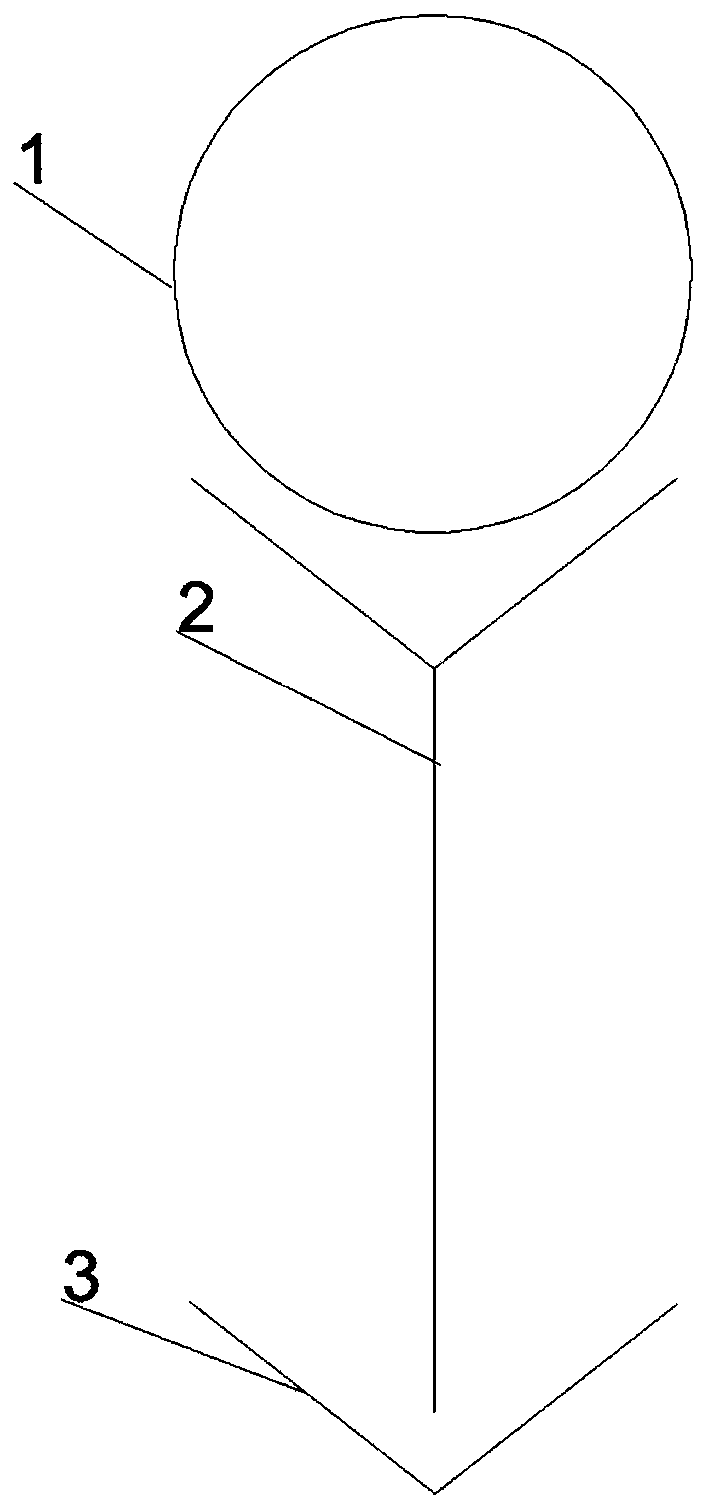
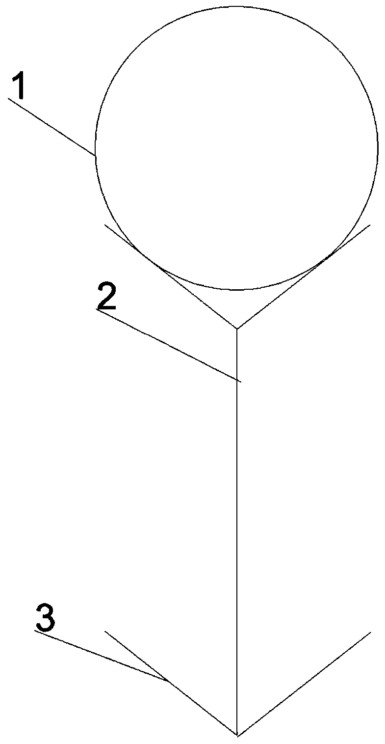
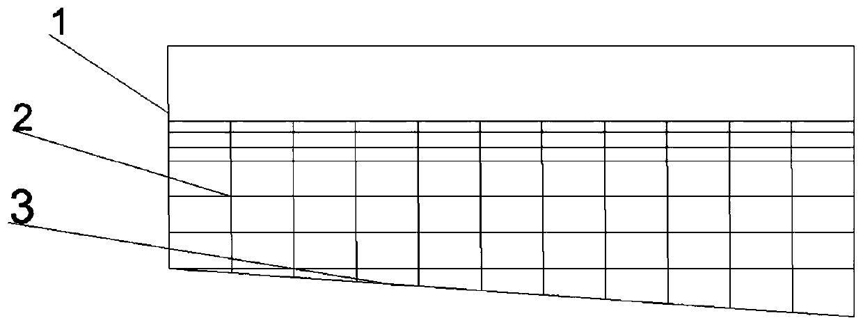
[0039] The radiant cooling ceiling structure of this embodiment includes cold water pipes, drainage plates and drainage plates. A drainage plate and drainage plate are arranged under each cold water pipe. The lower parts of the drainage plates are all in contact with the upper surface of the drainage plate. and the outer surface of the drainage plate are coated with hydrophobic material; the upper surface of the drainage plate is coated with hydrophobic material, the lower surface of the drainage plate is coated with hydrophilic material, and the section of the drainage plate is V-shaped, with a V-shaped channel , the diverter plate contacts the bottom of the V-shaped groove (see figure 1 and figure 2 ). Along the length of the drainage board, the angle between the bottom plane of the drainage board and the horizontal direction is 7° during installation, and the lower side of the drainage board is connected to the collection device. The sectional shape of the diversion plat...


PUM


Abstract

The invention discloses a radiation-refrigerating ceiling structure. The radiation-refrigerating ceiling structure comprises cold water tubes, drainage plates and water drainage plates, wherein one drainage plate and one water drainage plate are arranged below each cold water tube, the lower part of the drainage plate is in contact with the upper surface of the water drainage plate, a hydrophobicmaterial is coated on the outer surface of each of the cold water tube and the drainage plate, a hydrophobic material is coated on the upper surface of the water drainage plate, a hydrophilic materialis coated on the lower surface of the water drainage plate, an included angle between the bottom end plane of the water drainage plate and the horizontal direction during mounting is 5-8 degrees in alength direction of the water drainage plate, and the relatively low side of the water drainage plate is connected with a collecting device. The structure can solve the formed dew drop problem generated by water source ceiling radiation-refrigerating, and is especially suitable for an indoor high-humidity environment.

Description

technical field [0001] The invention relates to the technical field of indoor cooling ceiling air conditioning systems, in particular to a radiation cooling ceiling structure. Background technique [0002] At present, the cooling method of the air-conditioning system is basically based on convection heat transfer. This cooling method has poor comfort and ventilation, and consumes a lot of power. The roof air conditioning system based on radiation heat exchange can greatly improve the above shortcomings. However, during the cooling process, since the surface temperature of the suspended ceiling is generally lower than the dew point temperature of the air, water vapor in the air will condense on the surface. The dripping water droplets will affect the comfort of the living environment, and at the same time affect the cooling effect. If it is not removed for a long time, it will breed bacteria and accelerate the corrosion of the roof. Therefore, it is very important to develop...

Claims


Application Information

Patent Timeline
Patent Type & Authority Applications(China)
IPC IPC(8): F24F5/00F24F13/22E04B9/00
CPCF24F5/0092F24F13/222E04B9/00E04B9/006
Inventor 陈占秀乔达闵春华张石重
Owner HEBEI UNIV OF TECH
Learn More