Ammonia recovery process and equipment for non-ferrous metal metallurgical industry

A technology for the recovery of non-ferrous metals and ammonia, applied in the field of ammonia recovery, can solve the problems of low efficiency of bubble-cap trays, affecting normal production, affecting normal operation, etc., to improve production efficiency and economic benefits, good economic and environmental benefits, Good effect of self-cleaning ability

Inactive Publication Date: 2012-01-04
TIANJIN CHUANGJU TECHNOLGOY +1
View PDF3 Cites 7 Cited by
  • Summary
  • Abstract
  • Description
  • Claims
  • Application Information

AI Technical Summary

Problems solved by technology

Due to the low efficiency of the bubble-cap tray, the ammonia content in the liquid phase at the bottom of the tower is high, which seriously exceeds the requirements of environmental protection indicators, thereby affecting the normal operation of subsequent processes; normal pressure operation and low ammonia removal rate make the tower top After the ammonia vapor is condensed by the condenser, only ammonia water with a mass concentration of about 5% can be obtained
On the one hand, the ammonia water cannot be recycled because the concentration is too low; on the other hand, most of the u

Method used


Image

  • Ammonia recovery process and equipment for non-ferrous metal metallurgical industry
  • Ammonia recovery process and equipment for non-ferrous metal metallurgical industry

Examples


Embodiment 1

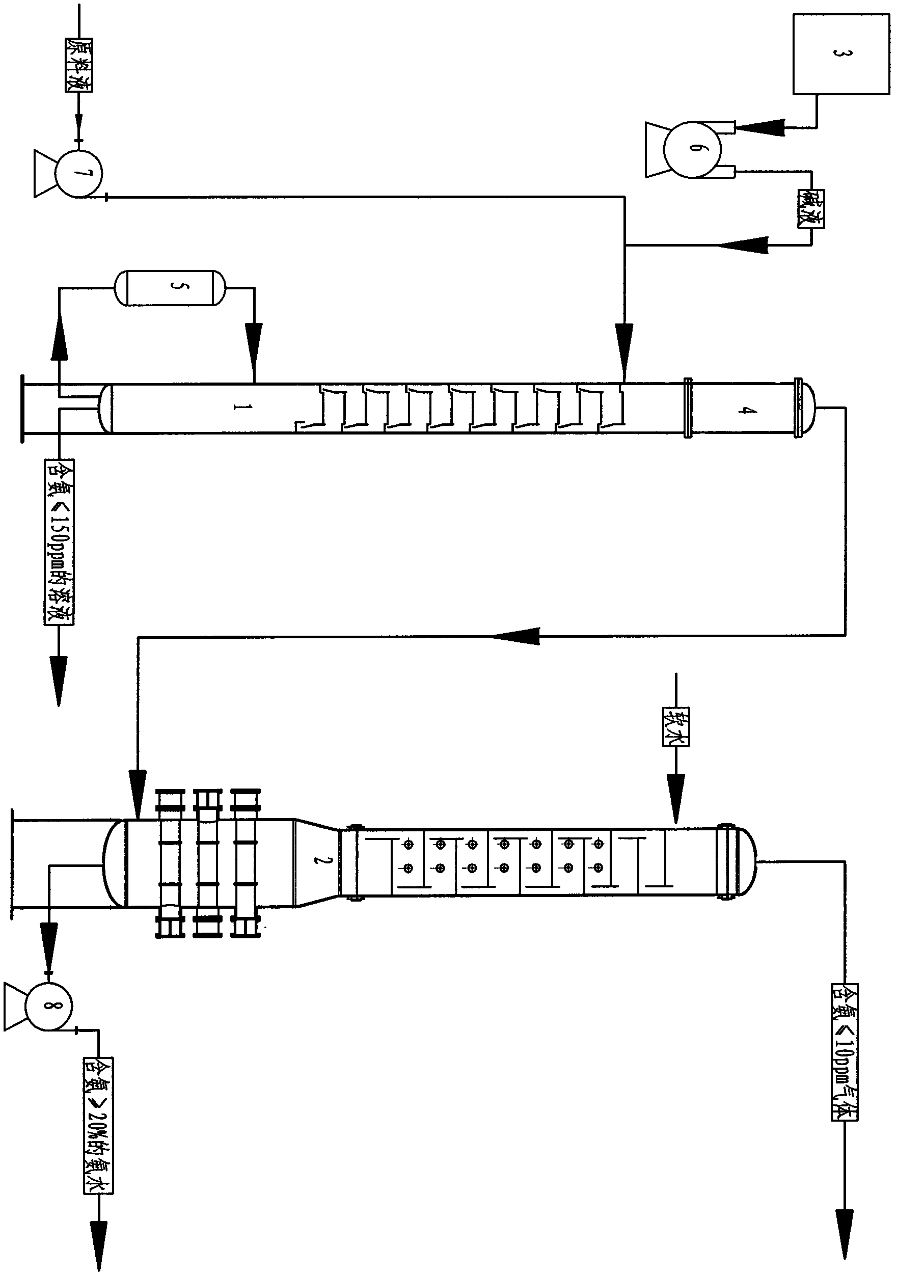
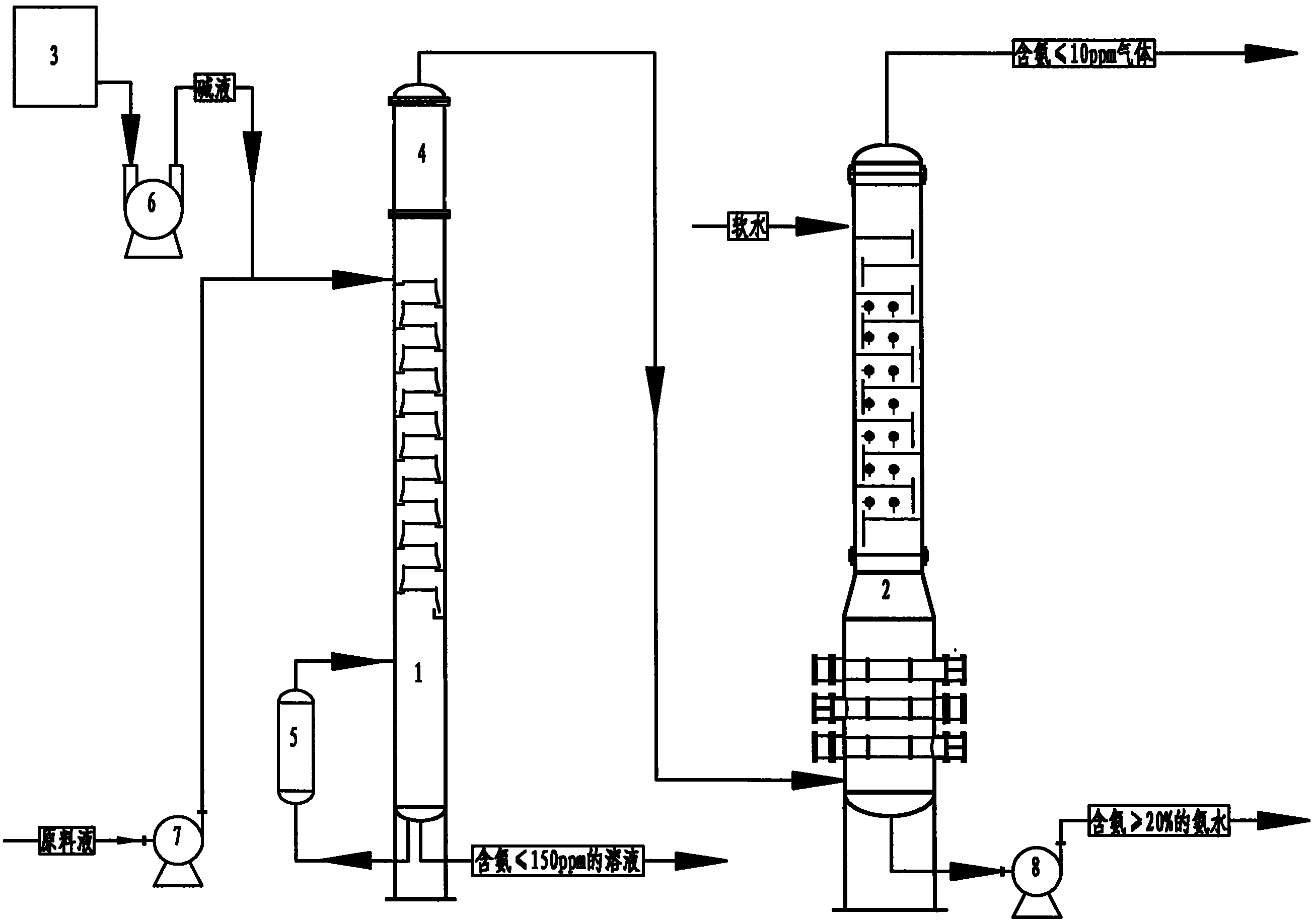
[0022] Alkali 0.25 ton / ton of raw material liquid that mixes alkali tank 3, alkali lye is the NaOH aqueous solution of mass concentration 40%, after lye pump 6 pressurization, with raw material liquid 4 tons / hour (the total of 25% of mass concentration Ammonia content) after raw material pump 7 pressurization, after the two are mixed in pipeline, be sent to the top of ammonia distillation tower 1 (operating pressure 0.3MPa gauge pressure, tray layer number 15 layers), the ammonia in raw material liquid is by The steam provided by the reboiler 5 is stripped and removed, and the solution with an ammonia content of 150 ppm is obtained at the bottom of the ammonia distillation tower 1, and is sent to the next process; the vapor phase ammonia at the top of the ammonia distillation tower 1 passes through the ammonia splitter 4 After condensation, high-concentration ammonia vapor (mass concentration 70%) is obtained and enters the bottom of ammonia recovery tower 2 (operating pressure...

Embodiment 2

[0024]The NaOH aqueous solution 0.5 ton / ton raw material liquid of the mass concentration 20% that comes from alkali tank 3, after lye pump 6 pressurization, with raw material liquid 4 tons / hour (the total ammonia content of mass concentration 25%) through raw material pump 7. After pressurization, after the two are mixed in the pipeline, they are sent to the top of the ammonia distillation tower 1 (working pressure 0.5MPa gauge pressure, 20 tray layers), and the ammonia in the raw material liquid is provided by the reboiler 5. The steam is stripped and removed, and the bottom of the ammonia distillation tower 1 obtains a solution with an ammonia content of 120 ppm, which is sent to the next process; the vapor-phase ammonia at the top of the ammonia distillation tower 1 is condensed by the ammonia splitter 4 to obtain a high concentration. Ammonia vapor (mass concentration 70%) enters the bottom of ammonia recovery tower 2 (operating pressure 0.35MPa gauge pressure, 15 layers o...

Embodiment 3

[0026] 1 ton / ton of NaOH aqueous solution 1 ton / ton raw material liquid of the mass concentration 10% that comes from alkali tank 3, after lye pump 6 pressurization, with raw material liquid 4 tons / hour (the total ammonia content of mass concentration 25%) through raw material pump 7 After pressurization, after the two are mixed in the pipeline, they are sent to the top of the ammonia distillation tower 1 (working pressure 0.7MPa gauge pressure, 35 layers of trays), and the ammonia in the raw material liquid is provided by the reboiler 5. The steam is stripped and removed, and the bottom of the ammonia distillation tower 1 obtains a solution with an ammonia content of 100 ppm, which is sent to the next process; the vapor-phase ammonia at the top of the ammonia distillation tower 1 is condensed by the ammonia splitter 4 to obtain a high concentration. Ammonia vapor (mass concentration 70%) enters the bottom of ammonia recovery tower 2 (operating pressure 0.55MPa gauge pressure, ...


PUM


Abstract

The invention discloses an ammonia recovery process and equipment for a non-ferrous metal metallurgical industry. The process comprises the following steps: mixing a base liquid with a raw material liquid in a pipeline and then feeding a mixed liquid to the upper part of an ammonia still, and carrying out steam stripping to remove ammonia in the raw material liquid; feeding a low-ammonia aqueous solution obtained at the bottom of the ammonia still to the next process; condensing gas-phase ammonia on the top of the ammonia still in an ammonia dephlegmator so as to obtain high-concentration ammonia gas; feeding the high-concentration ammonia gas into the bottom of an ammonia recovery tower to be absorbed by soft water; and recovering and recycling the high-mass-concentration ammonia water obtained at the bottom of the ammonia recovery tower, and evacuating trace fixed gas at the top of the ammonia recovery tower. The equipment is suitable for the ammonia recovery process disclosed by the invention and mainly comprises the ammonia still and the ammonia recovery tower, wherein the upper part of the ammonia still is in pipe connection with an alkali formulating tank through an alkali liquid pump and in pipe connection with a raw material liquid through a raw material pump; the ammonia dephlegmator is arranged inside the upper part of the ammonia still, and the lower part of the ammonia still is externally connected with a reboiler and is in pipe connection with the upper part of the ammonia still; and the kettle bottom of the ammonia recovery tower is in pipe connection with an ammonia water pump, the upper part of the ammonia recovery tower is in pipe connection with a soft water pipe, and the top of the ammonia recovery tower is provided with a discharge pipe.

Description

technical field [0001] The invention relates to an ammonia recovery technology in the chemical industry, in particular to an ammonia recovery process and equipment used in the nonferrous metal metallurgy industry. Background technique [0002] During the production of non-ferrous metals, a large amount of aqueous solution containing solid particles, volatile ammonia, non-ferrous metal ions, and complexes of non-ferrous metal ions and ammonia (referred to as raw material solution) is often produced. The raw material solution needs to be processed through ammonia recovery, and the volatilized ammonia and ammonia complexed with metal ions are removed to obtain a solution containing ammonia ≤ 150ppm, which is sent to the next process, and the removed ammonia is made into a solution with a mass concentration ≥ 20 % ammonia water, return to the previous process, recycle and reuse. [0003] The existing ammonia recovery process is as follows: the raw material liquid is sent to a b...

Claims


Application Information

Patent Timeline
IPC IPC(8): C01C1/02
Inventor 王柱祥商恩霞林长青马弘邵晓东魏美迎
Owner TIANJIN CHUANGJU TECHNOLGOY
Why Eureka
Try Eureka