
A large flow and large aspect ratio blade axial flow fan

A technology with large aspect ratio and blade shaft, which is used in the field of cooling ventilation and large-flow axial flow fans. It can solve the problems of overloading the fan drive motor and failing to meet energy-saving requirements, and achieve a uniform and stable inlet flow field and a simple airfoil. And effective, large flow effect

Active Publication Date: 2015-12-09
DALIAN UNIV OF TECH
View PDF3 Cites 0 Cited by
  • Summary
  • Abstract
  • Description
  • Claims
  • Application Information

AI Technical Summary

Problems solved by technology

[0003] Due to changes in operating conditions of domestic high-power and high-speed locomotives, the original brake resistor cooling fan can no longer meet the new operating conditions. If the original fan meets the higher outlet air pressure requirements simply by increasing the speed, it will There is a danger of overloading the fan drive motor, and it does not meet the energy saving requirements

Method used


Image

  • A large flow and large aspect ratio blade axial flow fan
  • A large flow and large aspect ratio blade axial flow fan
  • A large flow and large aspect ratio blade axial flow fan

Examples


Embodiment 1

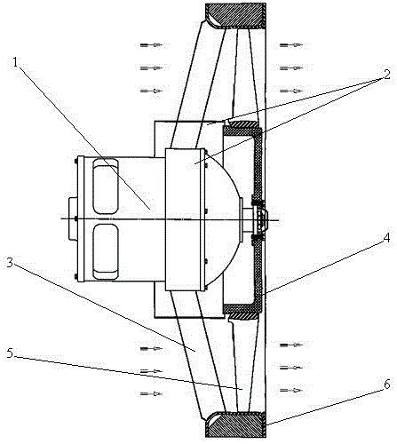
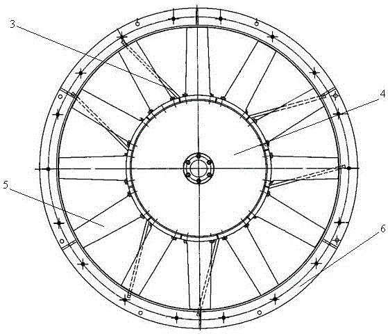
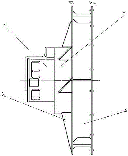
[0021] Such as figure 1 The blade-type axial flow fan with large flow and large aspect ratio shown in -3 is composed of a driving motor 1 , an inner support ring 2 , a support plate 3 , a hub 4 , blades 5 and a connecting duct 6 . The drive motor 1 is front mounted and connected to the inner support ring 2 by bolts, the inner support ring 2 is fixed on the support plate 3 by welding, and the support plate 3 is fixed on the connecting air duct 6 by welding, so that the drive motor 1 and the connection The relative position of air duct 6 has been fixed; blade 5 is connected with wheel hub 4 by bolts to form a rotatable impeller, and wheel hub 4 is connected with the shaft of drive motor 1 by coupling, so that blade 5 and wheel hub 4 are connected with respect to the shaft of air duct 6. The position is fixed, so that the relative positions of all parts of the whole fan are fixed. In this example, the impeller blade 5 adopts 12 pieces, and the blade 5 is as Figure 4 All shown ...

Embodiment 2

[0024] Large flow rate and large aspect ratio blade type axial flow fan, the basic structure is the same as that of embodiment 1. In this example, 10 impeller blades 5 are used, and the blades are all large aspect ratio blades, with an average aspect ratio of 2 and 5 blade roots. The installation angle is 25°, the joint between the blade and the tenon is rounded, the chamfering radius is 10m, and there are 3 pieces (three sets) of equal-thickness support plates 3 with diversion function welded between the connecting air duct 6 and the inner support ring 2 .

Embodiment 3

[0026] Large flow and large aspect ratio blade type axial flow fan, the basic structure is the same as that of embodiment 1. In this example, 15 impeller blades 5 are used, and the blades are all large aspect ratio blades, with an average aspect ratio of 3.5 and 5 blade roots. The installation angle is 35°, the joint between the blade and the tenon is rounded, and the chamfering radius is 25m. There are 9 pieces (three sets) of equal-thickness support plates 3 with diversion function welded between the connecting air cylinder 6 and the inner support ring 2 .


PUM


Abstract

The invention belongs to the technical field of fans and relates to a high-flow axial flow fan with high-aspect-ratio blades. The axial flow fan is characterized by being composed of a driving motor, an inner support ring, a support plate, a hub, blades and a connecting air duct and the like. The motor is fixed on the inner support ring through a bolt, the inner support ring is connected with the connecting air duct through the support plate, and the hub is directly connected with a motor shaft. The working wheel blades are in a high-aspect-ratio and independent mode, a working wheel can have high pressurization and through-flow capabilities under the conditions that the rotating speed is not changed, the axial dimensions of the fan are effectively reduced, the blades and a tenon are of an integrated structure and are fixed on the hub through bolts, and simultaneously the advantages that the blades can be independently processed and are convenient to dismantle and replace are guaranteed. Air flow enters from a front end air inlet, flows through the driving motor and the inner support ring, and enters the working wheel to be accelerated and pressurized. After passing through the working wheel, the air flow obtains enough speed and pressure to enter a brake resistor unit cooling module connected at a rear segment so as to achieve enough cooling effect.

Description

technical field [0001] The invention belongs to the technical field of ventilators, and relates to a large-flow axial flow fan, which is applied to the cooling and ventilating of a locomotive braking resistor unit and related equipment. Background technique [0002] With the continuous improvement of domestic high-power locomotives' operating speed and load capacity, it not only leads to a substantial increase in the heat generated by the locomotive power equipment, but also brings a greater load to the locomotive braking system, making the brake resistor unit The number and calorific value increased significantly. In order to ensure the safe and stable operation of the locomotive, the requirements for the cooling fan of the special heat-generating components of the locomotive are constantly increasing. At present, most of the cooling fans for locomotives in my country are imported fans. When the operating environment of locomotives changes, imported fans have long procurem...

Claims


Application Information

Patent Timeline
Patent Type & Authority Patents(China)
IPC IPC(8): F04D29/38F04D29/32F04D25/08
Inventor 王晓放杨晓清徐胜利刘海涛吴联军姜治迅薛家好
Owner DALIAN UNIV OF TECH
Learn More