Medium-voltage electric distribution apparatus

A technology of power distribution equipment and equipment, applied in the direction of high-voltage/high-current switches, circuits, electric switches, etc., can solve problems such as unreasonable industrial costs, complex molding, and complicated current conduction functions

Active Publication Date: 2013-04-03
SCHNEIDER ELECTRIC IND SAS
View PDF8 Cites 4 Cited by
  • Summary
  • Abstract
  • Description
  • Claims
  • Application Information

AI Technical Summary

Problems solved by technology

[0004] When the rated current performance of such switchboards or any similar switchboards has to be increased, large investments and excessive changes in operation are required, especially when these switchboards use complex technologies such as armored metal insulation technology
[0005] Furthermore, the fact that these switchboards are able to withstand higher power ratings than the usual mid-range corresponds to a range with a smaller footprint, causing the industrial cost of such a retrofit is not justified
In the case of vacuum circuit breakers, the current conducting function is further very complex and problematic, due to the reduced size of the contacts of the contact box, and their high contact resistance, which increases with the short-circuit operation performed changes in the number of
[0006] Furthermore, the development of such high-current switchboards increases the number of subassembly benchmarks, not to mention all the necessary peripheral improvements involving the main functions of the switchboard, namely, the dielectric and current distribution functions, which in specific cases require this electrical function to be derived from Intricate molding of the cast housing

Method used


Image

  • Medium-voltage electric distribution apparatus
  • Medium-voltage electric distribution apparatus
  • Medium-voltage electric distribution apparatus

Examples


Embodiment Construction

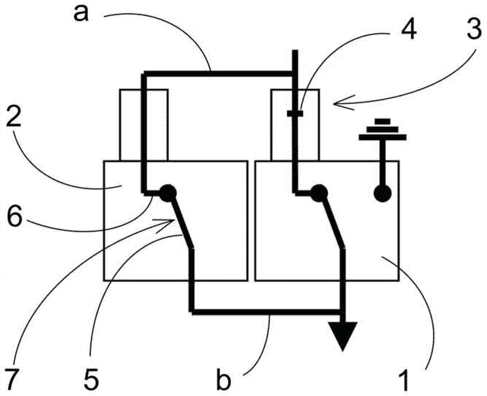
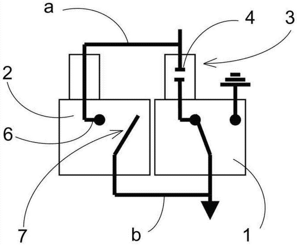
[0034] exist figure 1 and 2 In , there can be seen a multi-pole motorized switchgear comprising, for each pole, two switchboards 1, 2 mounted in parallel and electrically connected on one side to the first busbar 1a and on one side The opposite side is connected to the second busbar b.

[0035] The first switchboard 1 , located on the right in the figure, comprises in this particular embodiment a vacuum circuit breaker 3 comprising a vacuum box 4 connected in series with a disconnector 5 having two positions, respectively for the closed and grounded positions.

[0036] A second switchboard, located to the left of the first switchboard, includes a disconnect switch having two positions, a closed current flow position and an open position.

[0037] The two switchboards are mechanically connected so as to follow a specific sequence, which will be detailed below.

[0038] exist figure 1 , the equipment is in the closed position, and since the circuit breaker and disconnector ...


PUM


Abstract

The invention relates to a electric distribution apparatus comprising a circuit breaker device or interrupting device which is named as a first device, and an electric isolation device named as a second device. The first device and the second device are connected in parallel and occupying open and closed positions of a switching device. The two electric devices may use a first position and a second position. The opening and closing of the first and the second electric devices are controlled by the first electric device. When the switching device is moved from the closing position to the opening position, the contact of the isolation device is firstly opened. Arc and arc voltage generate between contacts so that current is switched to the breaker device or interrupting device. before the contact of the breaker device or interrupting device is opened, the contacts are open till the ample gap generates between contacts of the isolation device. Therefore, after contacts of two devices are closed, when transient recovery voltage is established, any subsequent dielectric breakdown at the position of the isolation device is prevented.

Description

technical field [0001] The invention relates to a medium-voltage electrical distribution device installed between two parts of an electrical circuit so as to perform at least the functions of current flow between the two parts and interruption of the current in the event of an electrical fault. Background technique [0002] A switchboard of the type described above is known, for example, from patent application FR2940516. This switchboard includes a switch or circuit breaker, which also performs an off-switching function, and in series with this switch (or circuit breaker), includes a selector with at least two positions, a current-passing position and a grounding position. [0003] This switchboard is designed to conduct a current of 630A and is therefore not suitable for conducting higher current levels such as 1250A. [0004] When the rated current performance of such switchboards, or any similar switchboards, has to be increased, large investments and undue changes to o...

Claims


Application Information

Patent Timeline
Patent Type & Authority Applications(China)
IPC IPC(8): H01H33/666H01H9/26
CPCH01H33/126H01H33/6661
Inventor D.珀林D.塔米西尔F.皮蒂斯
Owner SCHNEIDER ELECTRIC IND SAS
Why Eureka
Try Eureka