Rectangular stirring pile-forming machine

A pile machine, rectangular technology, applied in sheet pile wall, construction, infrastructure engineering and other directions, can solve problems such as small overlap area and water leakage

Active Publication Date: 2013-05-15
TAIXING FIRST CONSTR INSTALLATION
View PDF5 Cites 8 Cited by
  • Summary
  • Abstract
  • Description
  • Claims
  • Application Information

AI Technical Summary

Problems solved by technology

[0002] At present, the pile machines for building cement-soil composite walls all use several rotating drill bits to drill and mix side b

Method used


Image

  • Rectangular stirring pile-forming machine
  • Rectangular stirring pile-forming machine
  • Rectangular stirring pile-forming machine

Examples


Embodiment Construction

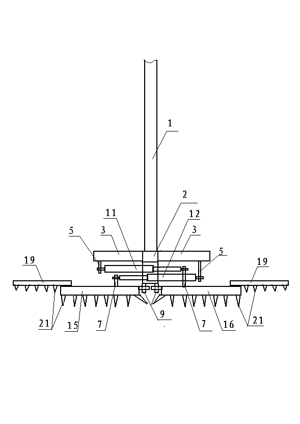
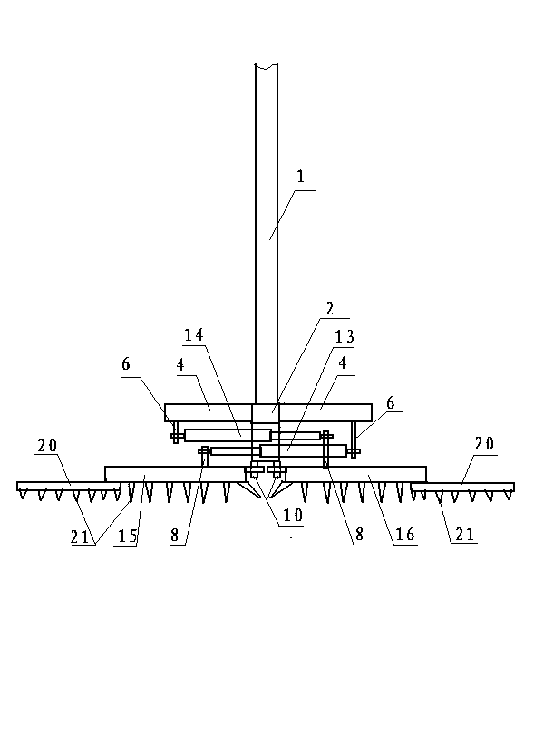
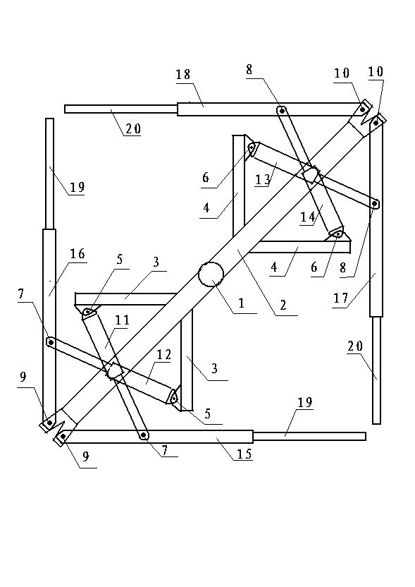
[0013] The accompanying drawing is a specific embodiment of the present invention. In this embodiment, the lower end of the drill pipe 1 is fixed in the middle of the beam 2. Two pivot pins F9 are arranged side by side at one end of the beam. One end of the knife arm A15 is pinned to a pivot pin F9. The upper part of the other end of A is fixed with a secondary knife arm A, one end of the knife arm B16 is pinned to another pivot pin F9, the other end of the knife arm B is fixed with a secondary knife arm A19, and the other end of the beam is arranged side by side with two pivot pins H10. One end of arm C is pinned to a pivot pin H10, the lower part of the other end of arm C is fixed with slave arm B, one end of arm D is pinned to another pivot pin H10, and the lower part of the other end of arm D is fixed with slave arm B20; Two support frames A are fixed on the beam on one side of the drill pipe. One end of the driving cylinder A11 is pinned to the support frame A through the ...


PUM


Abstract

The invention provides a rectangular stirring pile-forming machine. The lower end of a drilling rod is fixed in the middle of a cross beam. One end of the cross beam is parallelly provided with two shaft pins F. One end of a tool arm A is in pin joint connection with a shaft pin F, and a driven tool arm A is fixed on the upper portion of the other end of the tool arm A. One end of a tool arm B is in pin joint with the other shaft pin F, and a driven tool arm A is fixed on the upper portion of the other end of the tool arm B. The other end of the beam is parallelly provided with two shaft pins H. One end of a tool arm C is in pin joint with a shaft pin H, and a driven tool arm B is fixed on the lower portion of the other end of the tool arm C. One end of a tool arm D is in pin joint with the other shaft pin H, and a driven tool arm B is fixed on the lower portion of the other end of the tool arm D. A plurality of alley tool bits are evenly distributed on the tool arms and the lower portions of the tool arms. The rectangular stirring pile-forming machine can be of a rectangular cement-soil composite pile body.

Description

1. Technical field [0001] The invention relates to a pile forming machine, in particular to a rectangular mixing pile forming machine for building cement-soil composite walls. 2. Background technology: [0002] At present, the piling machines for building cement-soil composite walls all use several rotating drill bits to drill and mix side by side. The composite wall formed is a continuous side-by-side cylinder. The overlapping area is small, and the water leakage is serious. 3. Contents of the invention: [0003] The invention fills up the gap above and provides a rectangular stirring pile machine. [0004] The present invention is achieved through the following technical solutions: [0005] A rectangular mixing pile machine, the lower end of the drill rod is fixed in the middle of the beam, two pivot pins F are arranged side by side at one end of the beam, one end of the knife arm A is pinned to a pivot pin F, and the other end of the knife arm A is fixed with a slave ...

Claims


Application Information

Patent Timeline
IPC IPC(8): E02D5/46
Inventor 张璐
Owner TAIXING FIRST CONSTR INSTALLATION
Why Eureka
Try Eureka