
A Repairing Method for Broken Shaft

A repair method and technology for broken shafts, which are applied in the field of repairing broken shafts, can solve the problems of incomplete penetration, slag inclusion, and lack of fusion, so as to eliminate shear concentration stress parts, eliminate shear stress concentration and welding stress. Effect

Inactive Publication Date: 2016-12-07
BAOSHAN IRON & STEEL CO LTD
View PDF3 Cites 0 Cited by
  • Summary
  • Abstract
  • Description
  • Claims
  • Application Information

AI Technical Summary

Problems solved by technology

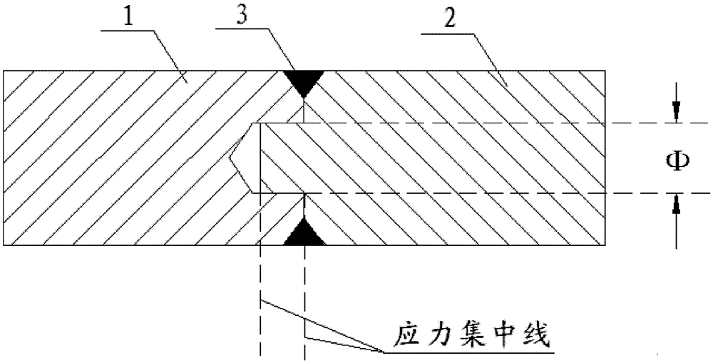
Besides, there is still welding residual stress after welding, but the residual stress of different methods is different. At the same time, due to the rapid cooling of the heat-affected zone, the welded parts are prone to quenched martensite and cracks under the condition of high carbon content. In addition, if the welding process is not properly controlled, defects such as pores, slag inclusions, incomplete fusion, and incomplete penetration are likely to occur. Therefore, the larger the welding surface (depth), the greater the welding stress, and the greater the possibility of welding cracks. Big

Method used


Image

  • A Repairing Method for Broken Shaft
  • A Repairing Method for Broken Shaft
  • A Repairing Method for Broken Shaft

Examples


Embodiment 1

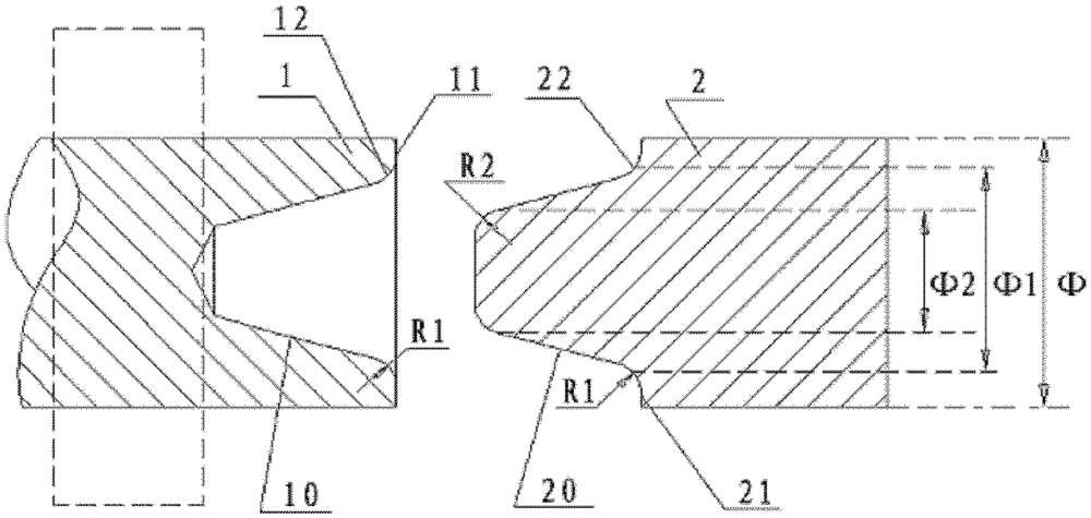
[0051] Example 1: Φ=150 mm, the material is 30 steel shaft shear fracture, and the main use section is reserved as the broken shaft section 1 . First, flatten the fracture surface 11 of the broken shaft section 1 and process the conical hole 10, the hole rounding R1=150, and then prepare the coupling shaft section 2 with a conical head 20 and coaxial diameter and rounding R1=150 And R2=300, the taper of the conical head 20 and the conical hole 10 is the same, and the taper is 10°~12°. Match the conical head 20 of the connecting shaft section 2 at room temperature to determine the distance of a, which is 15mm, and then process the spacer ring 3 with a height h of nine tenths of a, which is 13-14mm, and then insert the spacer ring 3 into the shaft connecting section 2 At the tail of the conical head 20, the gas flame heats the conical hole 10 of the broken shaft section 1 to 400°C within 5 minutes, and pushes the conical head 20 into the conical hole 10 to the root, and cools fr...

Embodiment 2

[0052] Example 2: Φ=100 mm, the gear shaft made of No. 45 steel is sheared and fractured, and the broken shaft at the gear end that has not been disassembled is kept as the broken shaft section 1 . First process the fracture surface 11 of the broken shaft section 1 to flatten and process the conical hole 10, the hole rounding angle R1=50, and then prepare the coupling shaft section 2 with the conical head 20 coaxial diameter and round the corner R1=50 and R2=100, the taper of the conical head 20 and the conical hole 10 is the same, and the taper is 10°~12°. The connecting shaft section 2 is selected from No. 35 or 40 steel, preferably No. 40 steel, and then the conical hole 10 of the broken shaft section 1 and the The conical head 20 of the connecting shaft section 2 is matched at room temperature to determine the distance of a, which is 10 mm, and the processing height h is nine tenths of a, which is 9 mm. , the gas flame heats the conical hole 10 of the broken shaft section ...

Embodiment 3

[0053] Example 3: Φ = 50mm, material 35 steel is sheared and fractured, and the broken shaft at the main use end is reserved as the broken shaft section 1 . First, the fracture surface 11 of the broken shaft section 1 is gold-processed and flattened, and the conical hole 10 is processed, and the hole is rounded R1=25. Next, prepare the connecting shaft section 2 with the conical head 20 and the coaxial diameter and fillet R1=25 and R2=50. The taper of the conical head 20 and the conical hole 10 is the same, and the taper is 10°~12°. The connecting shaft section 2 is selected. 25 or 30 steel, preferably 30 steel. Then match the conical hole 10 of the broken shaft section 1 with the conical head 20 of the connecting shaft section 2 at room temperature to determine the distance of a, which is 10 mm, and the processing height h is nine tenths of a, which is 4 mm spacer ring 3, and then set the spacer ring 3 sets Enter the tail of the conical head 20 of the connecting shaft sectio...


PUM


Abstract

The invention discloses a repair method of a fracture shaft. The method comprises the following steps that a fracture shaft section with an original diameter phi is reserved, firstly a fracture surface of the fracture shaft section is machined smoothly, a conical bore is formed in the fracture surface of the fracture shaft section, then a round corner with a radius of R1 is chamfered in a bore opening of the conical bore, a connecting shaft section with the diameter phi and with a conical head on the front end surface is assembled, a round corner with a radius of R1 is chamfered in the tail portion of the conical head, and a round corner with a radius of R2 is chamfered in the head portion of the conical head; the conical head is freely embedded in the conical bore, an effective distance a between the fracture surface of the fracture shaft section and the front end surface of the connecting shaft section is kept, and a spacing ring with a height of H, the outer circle diameter phi and chamfering on two end surfaces is assembled; the shaft sections are heated to be in an effective temperature, then the spacing ring is sleeved on the tail portion of the conical head which is embedded in the conical bore by small force, free cooling to be in the normal temperature is carried out, and thus the spacing ring can freely rotate; and multiple filling pieces are respectively crammed into two end surfaces of the spacing ring, chamfering parts at two ends of the spacing ring are in sealing weld, and the fracture shaft is repaired to be smooth through normal temperature cooling.

Description

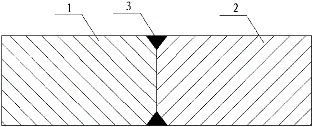
technical field [0001] The invention relates to a mechanical manufacturing method, in particular to a repair method for a broken shaft. Background technique [0002] Rotors and shafts such as motors or gears are sometimes twisted suddenly during operation. In the absence of suitable spare parts, the twisted shaft must be repaired in time to restore the equipment to work as soon as possible. It is the guiding principle of the repair work to protect the rotor and shaft from any damage during the repair work, and to ensure the firmness and quality of the repair. [0003] At present, one of the ways to repair the broken shaft is to use the groove direct welding method (see figure 1 ), that is, the fracture surface of shaft 1 and the fracture surface of shaft 2 are properly processed to form groove 3, and then connected by welding. The method of welding connection is relatively simple, but the welding strength is relatively weak, which is suitable for the connection of shaft f...

Claims


Application Information

Patent Timeline
Patent Type & Authority Patents(China)
IPC IPC(8): B23P6/04
Inventor 卢江海孔利明丁海绍
Owner BAOSHAN IRON & STEEL CO LTD
Learn More