Dual-purpose detonating device for detonating perforating gun

A technology of detonating device and perforating gun, which is applied in the direction of mining fluid, wellbore/well components, earthwork drilling and production, etc. It can solve problems such as non-compliance, many joint points, and inconvenient use by users, so as to meet the requirements of ensuring pressure resistance and ensuring Reliability, reliable effect

Active Publication Date: 2013-06-12
WUHUA ENERGY TECH CO LTD
View PDF6 Cites 3 Cited by
  • Summary
  • Abstract
  • Description
  • Claims
  • Application Information

AI Technical Summary

Problems solved by technology

A safety redundant detonating device proposed in patent ZL201120158524.5 is that the detonator part has a double ignition structure, but if the mechanical assembly part fails, normal detonation cannot be guaranteed
The known redundant annular space pressurized ignition system of Irving Company of the United States has a dual detonation sequence, but there are many problems: 1. It is a multi-joint split structure, and another detonation device must be connected before use, which is not a real The dual-effect detonating device in the sense causes great inconvenience to users
2. Huge volume, complex structure, do not use on-site assembly and construction
3. There are many joint points in the detonation transmission sequence, and the reliability of detonation transmission is reduced. 4. It can only be pressurized in the casing, which does not meet certain well conditions in domestic oil fields.

Method used


Image

  • Dual-purpose detonating device for detonating perforating gun
  • Dual-purpose detonating device for detonating perforating gun
  • Dual-purpose detonating device for detonating perforating gun

Examples


Embodiment Construction

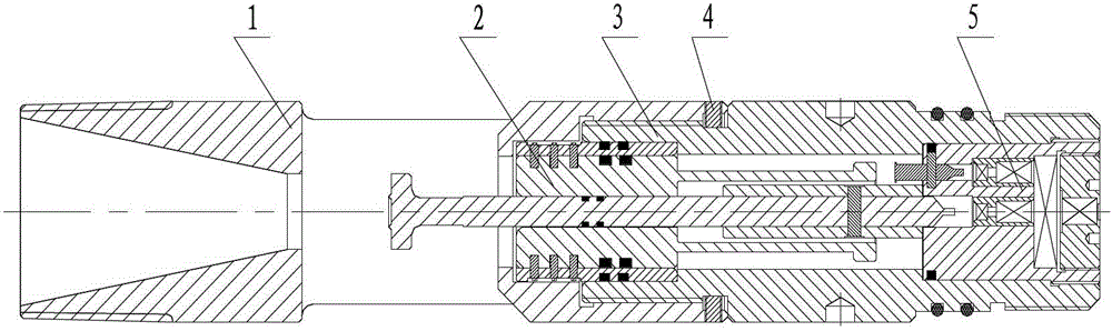
[0032] Now in conjunction with embodiment, accompanying drawing, the present invention will be further described:

[0033] as figure 1 As shown, the preferred embodiment of the present invention includes an upper body 1, a piston assembly 2, a lower body 3, a screw 4, an explosion assembly 5 and several sealing rings. The upper body 1 is a hollow cylinder made of 40Cr steel and is provided with a variable cross-section through hole along the axis. The outside of the input end is provided with an external thread for connecting the oil pipe, the inside is a through hole with variable cross-section, and the inside of the output end is provided with an internal thread hole for connecting the lower body 3 . A rectangular sand discharge window is symmetrically opened in the center of the pipe wall, and four screw holes are evenly distributed on the outside of the output end. The lower body 3 is made of 40Cr steel, the outer side of the input end is an external thread connected to ...


PUM


Abstract

The invention relates to a dual-purpose detonating device for detonating a perforating gun, which is characterized by comprising an upper body, a piston component, a lower body and a detonating component, wherein the upper body and the lower body are fixedly connected through screws; the piston component and the detonating component are sequentially arranged in a through hole; a nailhead end of a ramming piston of the piston component is arranged in the upper body and in the through hole matched with the nailhead end, and the nail point end thereof is arranged in a axle center through hole of a pin striking seat of the detonating component; three steps are arranged in the through hole formed by the upper body and the lower body; a pressure piston sleeve is clamped between two middle steps; the width of each step is equal to the thickness of the pressure piston sleeve; and the detonating component is connected with the step at the bottom of the lower body. The detonating device provided by the invention, which is suitable for tubing conveyed perforating operation of an oil and gas well, has the advantages of compact structure, complete assembly, and reliable function, has two-path detonating functions of rod throwing and pressurizing, and integrates the efficacy of striking detonating and wellhead pressurizing detonating.

Description

technical field [0001] The invention relates to a double-effect detonating device, in particular to a detonating device suitable for detonating a perforating gun in an oil and gas well oil pipe transmission perforation operation. Background technique [0002] The operation methods of detonating devices used in perforating oil and gas wells are divided into rod-throwing and impact detonation, pressure detonation, and combined impact and pressure detonation. Generally, the excitation form of the detonation device can only choose one way to detonate, and there are many uncertain factors in the construction process, such as the phenomenon of hanging rods in the process of using the anti-sand detonation device, so that the rod cannot hit the piston and cannot Detonating the detonating device will cause rework, and at the same time there will be a huge safety hazard, which may cause misperforation or personnel accidents. Simultaneously, the currently used detonating devices gener...

Claims


Application Information

Patent Timeline
Patent Type & Authority Applications(China)
IPC IPC(8): E21B43/1185
Inventor 肖勇王雪艳魏领章松桥刘正彦
Owner WUHUA ENERGY TECH CO LTD
Why Eureka
Try Eureka