Structure for continuous transformation of existing simply supported hollow slab girder bridge and construction method of structure

A construction method and hollow slab technology, applied in bridges, bridge parts, bridge maintenance, etc., can solve the problems of low tensile strength of filling materials, small continuous space in the joint area, and difficult reconstruction of old bridges, and achieve good seismic effect and overall The effect of good performance and low renovation cost

Active Publication Date: 2013-07-17
FUZHOU UNIV
View PDF8 Cites 6 Cited by
  • Summary
  • Abstract
  • Description
  • Claims
  • Application Information

AI Technical Summary

Problems solved by technology

Although the first two construction methods can improve the cracking of the bridge deck at the support to a certain extent, they cannot be fundamentally improved due to the small continuous space in the joint area and the low tensile strength of the filling material (such as concrete). Resist the negative bending moment generated at the joints after the simply supported beam is continuous, which will also lead to cracking of the bridge deck; while the construction method of bridge deck (slab) continuous + wet joint + prestress can be avoided by applying local prestress Cracking of the bridge deck, but this method is complex in construction, and applying prestress in a small area is likely to cause local stress concentration, and the loss of prestress is also large, and it is difficult to use in the reconstruction of old bridges

Method used


Image

  • Structure for continuous transformation of existing simply supported hollow slab girder bridge and construction method of structure
  • Structure for continuous transformation of existing simply supported hollow slab girder bridge and construction method of structure
  • Structure for continuous transformation of existing simply supported hollow slab girder bridge and construction method of structure

Examples


Embodiment Construction

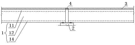
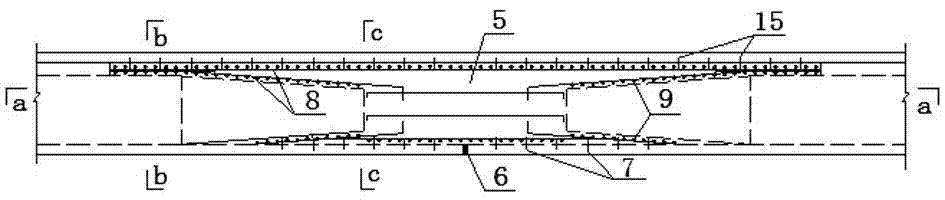
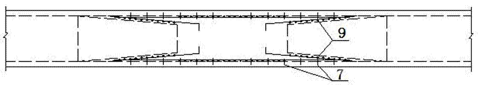
[0031] Such as Figure 1~9 As shown, a structure for the continuous reconstruction of an existing simply supported hollow slab girder bridge includes the hollow slab 1 and the pier 2 of the existing simply supported hollow slab girder bridge, and the two adjacent hollow slabs 1 on the top of the pier 2 are respectively Cut off part of the top plate 11 and part of the web 12 along the bridge direction, and form a Y-shaped joint 5 between the ends of the two hollow plates 1 after the chisel, and the Y-shaped joint 5 is equipped with steel bars and poured concrete to form The continuous section 10 of two hollow slabs 1 is connected, and the bridge deck pavement 3 is recast on the two hollow slabs 1 and the continuous section 10 .

[0032] In this embodiment, the chiseled length between the top plates 11 of the two hollow plates 1 is m, and the value of m is the range where there is a negative bending moment at the top of the continuous rear pier 2 . The chisel height of the uppe...


PUM


Abstract

The invention relates to a structure for continuous transformation of an existing simply supported hollow slab girder bridge. The structure comprises two hollow slabs and a pier of the existing simply supported hollow slab girder bridge, wherein part of top plates and part of web plates of the two adjacent hollow slabs on the top of the pier are removed through chiseling along the bridge direction; a Y-shaped seam is formed between the end parts of the two chiseled hollow slabs; reinforcing steel bars are laid and concrete is poured in the Y-shaped seam to form a continuous section connected with the two hollow slabs; and a bridge deck pavement is poured on the two hollow slabs and the continuous section again. The invention also relates to a construction method for the continuous transformation of the simply supported hollow slab girder bridge. According to the invention, a feasible and effective guidance method is provided for the continuous transformation of the existing simply supported hollow slab girder bridge, complex construction caused by prestress is avoided, and splits are effectively avoided. The structure is favorable in integrity, has good quake-proof and collapse-proof effects in earthquakes, and has the advantages of simplicity and convenience in construction and strong durability.

Description

technical field [0001] The invention relates to the technical field of civil engineering, in particular to a structure and a construction method for the continuous transformation of an existing simply supported hollow slab girder bridge. Background technique [0002] The simply supported beam bridge is a statically indeterminate structure, which has the characteristics of clear force, simple structure, convenient construction, easy maintenance, and no additional internal force due to uneven settlement of the foundation. It can be applied to situations with relatively poor geological conditions. Hollow slab simply supported girder bridges are often built in our country. In order to adapt to temperature changes and structural deformation caused by load, porous simply supported girder bridges usually have expansion joints on each pier (platform). Bridge expansion joints are the most vulnerable and difficult to repair parts of bridge structures. From the end of 1989 to the begi...

Claims


Application Information

Patent Timeline
Patent Type & Authority Applications(China)
IPC IPC(8): E01D19/06E01D19/00E01D22/00
Inventor 吴庆雄陈宝春韦建刚
Owner FUZHOU UNIV
Why Eureka
Try Eureka