Bearing ball installing groove detector

A technology of bearing balls and mounting grooves, which is applied in the direction of instruments, measuring devices, and mechanical devices, etc., can solve the problems of laborious and time-consuming detection work, lack of special tools for bearing ball mounting grooves, etc.

Inactive Publication Date: 2013-07-17
TONGHAI DAYU BEARING
View PDF4 Cites 4 Cited by
  • Summary
  • Abstract
  • Description
  • Claims
  • Application Information

AI Technical Summary

Problems solved by technology

[0003] The present invention aims at the problems in the prior art that the detection of the bearing ball installation groove lacks special tools, and the detection work is laborious and time-consuming. It provides a bearing ball installation groove detector. A fixed plate is installed on the base, and a wire is installed in the middle of the fixed plate. Rod, one end of the screw rod is equipped with a handle, a movable plate is installed on the surface of the fixed plate, a nut is fixed under the movable plate, the nut is set on the screw

Method used


Image

  • Bearing ball installing groove detector
  • Bearing ball installing groove detector

Examples


Embodiment

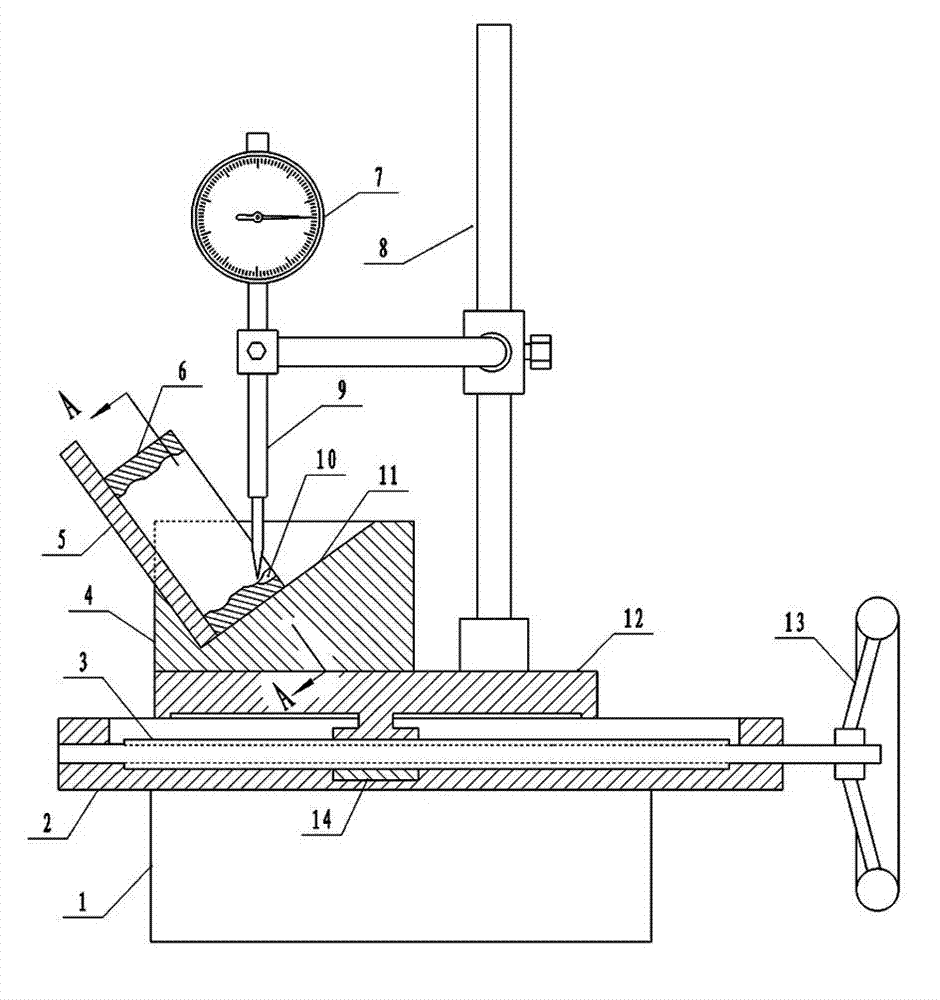
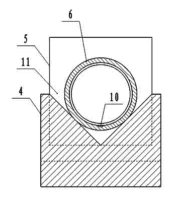
[0008] Example: such as figure 1 with figure 2 As shown, a bearing ball installation groove detector, a fixed plate 2 is installed on the base 1, a screw rod 3 is installed in the middle of the fixed plate 2, a handle 13 is installed on one end of the screw rod 3, and a handle 13 is installed on the surface of the fixed plate 2. Movable plate 12, a nut 14 is fixed under the movable plate 12, the nut 14 is set on the screw rod 3, a positioning block 4 is installed on the movable plate 12, and a "V" shaped chute 11 is designed on the locating block 4, and the chute 11 One end of the chute is equipped with a baffle 5, and the groove bottom of the chute 11 is consistent with the axial direction of the screw rod 3, and the included angle with the horizontal line is 36 0 , A fixed column 8 is installed next to the positioning block 4, and a dial indicator 7 is installed on the fixed column 8. The probe 9 of the dial indicator 7 is facing the bottom of the ball installation groove ...


PUM


Abstract

Provided is a bearing ball installing groove detector. A fixed plate is installed on a base, a lead screw is installed in the middle of the fixed plate, one end of the lead screw is provided with a handle, a movable plate is installed on the surface of the fixed plate, a nut is fixed under the movable plate and is sleeved on the lead screw, and a positioning block is installed on the movable plate. A V-shaped chute is designed on the positioning block, a blocking plate is installed at one end of the chute, and the chute bottom of the chute and the axial direction of the lead screw are consistent. An included angle is in a range from 300 to 450, a fixed column is installed beside the positioning block, a dial indicator is installed on the fixed column, and a probe of the dial indicator right faces the groove bottom of a ball installing groove on a bearing excircle. When the bearing ball installing groove detector is used, an operator turns the excircle to ensure the probe to right face the lowest point of the installing groove and turns the handle on the lead screw, the excircle performs horizontal movement, the dial indicator measures a height numerical value of a protruding edge in the installing groove and a low point of a bearing arc-shaped groove, and the accuracy of a notching position of the installing groove can be detected.

Description

technical field [0001] The invention belongs to the technical field of bearing testing equipment, and relates to a bearing ball installation groove detector. Background technique [0002] The balls of the ball bearing are installed in the arc-shaped grooves of the inner ring and the outer ring, and the distance between the balls is fixed by a retainer installed in the gap between the inner and outer rings. When the balls are installed into the arc groove between the inner and outer rings, the extrusion installation method is commonly used. This method is to squeeze the outer ring with a pressure device to produce a slight deformation, and arrange the balls to the bottom of the arc groove in the outer ring. Then install the inner ring, align the arc grooves, cancel the pressure on the outer ring, the balls will be loaded into the arc grooves, and then install the retainer to fix the distance between the balls. For some bearings with wider outer ring and thicker wall thicknes...

Claims


Application Information

Patent Timeline
IPC IPC(8): G01B5/00G01B5/02G01B5/18
Inventor 张永清张学禹李存航葛保儒杨崇明葛金
Owner TONGHAI DAYU BEARING
Why Eureka
Try Eureka