Bicycle pedal and manufacturing method thereof

A manufacturing method, bicycle technology, applied to vehicle components, crank structure, transportation and packaging, etc., can solve the problems of unavoidable knee joint pain, unfavorable knee joint protection, etc., and achieve the effect of avoiding pressure friction

Inactive Publication Date: 2013-07-24
SHANGHAI DIANJI UNIV
View PDF8 Cites 2 Cited by
  • Summary
  • Abstract
  • Description
  • Claims
  • Application Information

AI Technical Summary

Problems solved by technology

However, when riding a bicycle, the legs still need to be pedaled downward to drive the bicycle, causing the knee joint to rub under pressure, which is not conducive to knee joint protection, nor can avoid the pain caused by knee joint damage and friction

Method used


Image

  • Bicycle pedal and manufacturing method thereof
  • Bicycle pedal and manufacturing method thereof

Examples


Embodiment 1

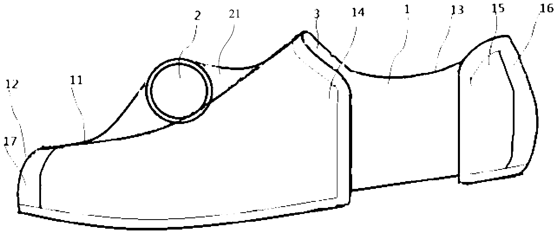
[0027] In this example, please refer to figure 1 , this embodiment provides a bicycle pedal, including a pedal body 1 and a rotating shaft 2, the pedal body 1 is used to accommodate the rider's feet, and from the front, rear, both sides and above the feet Five directions define the feet, and the force that the rider acts on the front, rear and top of the feet is transmitted to the rotation shaft 2 through the pedal body 1, and the rotation shaft 2 is arranged on the pedal body 1, And the rotation of the bicycle is driven by the rotation shaft 2 following the movement of the pedal body 1 . In the present invention, the movement of the pedal body can be counterclockwise rotation, clockwise rotation or swinging back and forth. The feet in this embodiment can also be regarded as shoes, because people usually wear shoes when riding a bicycle.

[0028] In this example, please refer to figure 1 , the pedal body 1 includes a back 11, a head 12, a heel 15, an inner side 13 and an ou...

Embodiment 2

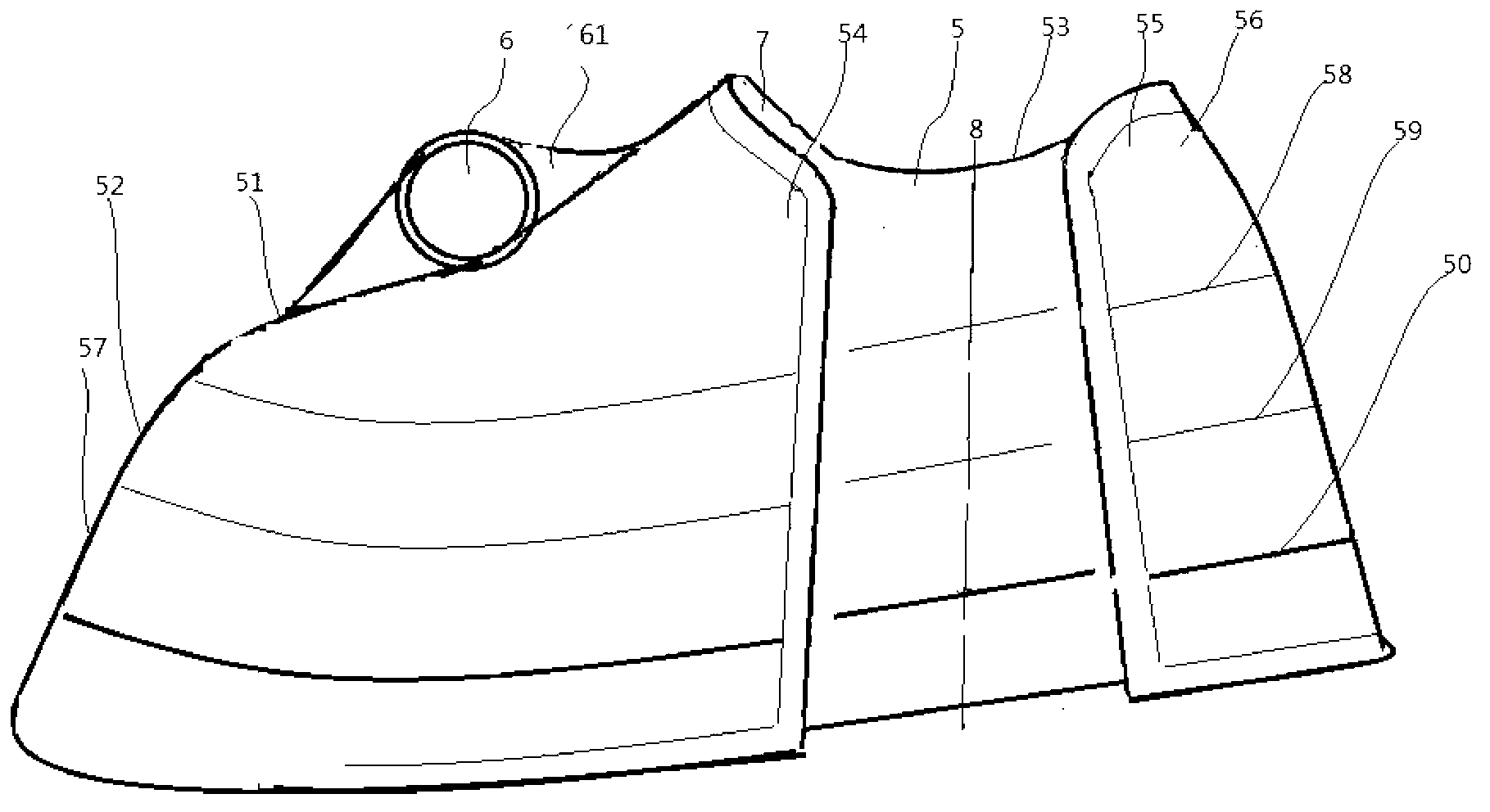
[0038] Please refer to figure 2 , the present embodiment provides a bicycle pedal, including a pedal body 5 and a rotating shaft 6, the pedal body 5 is used to accommodate the rider's feet, and from the front, rear, both sides and above the feet Five directions define the feet, and the force that the rider acts on the front, rear and top of the feet is transmitted to the rotation shaft 6 through the pedal body 5, and the rotation shaft 6 is arranged on the pedal body 5, And the rotation of the bicycle is driven by the rotation shaft 6 following the movement of the pedal body 5 . The feet in this embodiment can also be regarded as shoes, because people usually wear shoes when riding a bicycle. In this example, please refer to figure 2 , the pedal body 5 includes a back 51, a head 52, a heel 55, an inner side 53 and an outer side 54, and the back 51, the head 52, the heel 55, the inner side 53 and the outer side 54 are respectively connected with the riding The instep, the ...


PUM


Abstract

The invention provides a bicycle pedal and a manufacturing method thereof. The bicycle pedal comprises a pedal body and a rotating shaft. The pedal body is used for containing a foot of a rider and is used for limiting the foot from five directions including the front, the rear, two sides and the upper position. Force exerted on the front position, the rear position and the upper position of the foot by the rider is transferred to the rotating shaft through the pedal body. The rotating shaft is arranged on the pedal body, and a bicycle is driven to run by the fact that the rotating shaft operates along with the pedal body. Through the arrangement of the pedal body, the foot is limited from the five directions including the front, the rear, two sides and the upper position of the foot, a pedal bottom board is not arranged at the sole of the foot, namely the pedal is a bottomless shoe-shaped pedal, the rider can ride the bicycle to run through force from upward raising, forward pushing and backward pulling, the muscle such as quadriceps femoris is exercised, pressure friction of knee joints can be avoided or reduced, and the pedal is beneficial for delaying degenerative change of the knee joints and improving living quality of patient groups.

Description

technical field [0001] The invention relates to a human-powered bicycle and bicycle fitness equipment, in particular to a bicycle pedal and a manufacturing method thereof. Background technique [0002] The human knee joint has a limited number of friction loads. Age growth or long-term and excessive use will lead to irreversible wear and lesions of the knee joint. In severe cases, it will cause pain, difficulty in walking, and inconvenience in life, and then the formation of leg muscles. atrophy and deformity of the legs. However, reduced knee mobility can affect work and quality of life, as well as exercise in other parts of the body. Cycling can properly reduce the load pressure on the knee joint, change the worn part of the knee joint, reduce the wear degree of the knee joint, and at the same time effectively exercise the muscles of the legs and improve travel efficiency. However, when riding a bicycle, the legs still need to be pedaled downward to drive the bicycle, ca...

Claims


Application Information

Patent Timeline
Patent Type & Authority Applications(China)
IPC IPC(8): B62M3/08
Inventor 计春雷赵风景赵阳
Owner SHANGHAI DIANJI UNIV
Why Eureka
Try Eureka