Electronic component installation apparatus and electronic component installation method

A technology for electronic component installation and electronic components, applied in the direction of electrical components, electrical components, etc., can solve problems such as expensive and limited, and achieve the effect of efficient and high-precision installation

Active Publication Date: 2013-08-14
JUKI CORP
View PDF4 Cites 11 Cited by
  • Summary
  • Abstract
  • Description
  • Claims
  • Application Information

AI Technical Summary

Problems solved by technology

Therefore, the types of electronic components that can be mounted corresponding to the types of mounting heads mounted on the mounting device are limited, and since there are various types of mounting heads, it becomes a very expensive device.

Method used


Image

  • Electronic component installation apparatus and electronic component installation method
  • Electronic component installation apparatus and electronic component installation method
  • Electronic component installation apparatus and electronic component installation method

Examples


Embodiment Construction

[0159] Hereinafter, the present invention will be described in detail with reference to the accompanying drawings. In addition, this invention is not limited by the form (henceforth embodiment) for carrying out the invention mentioned below. In addition, the constituent elements in the following embodiments include elements within the so-called equivalent range, such as elements that can be easily conceived by those skilled in the art, substantially the same elements, and the like. In addition, components disclosed in the following embodiments may be appropriately combined.

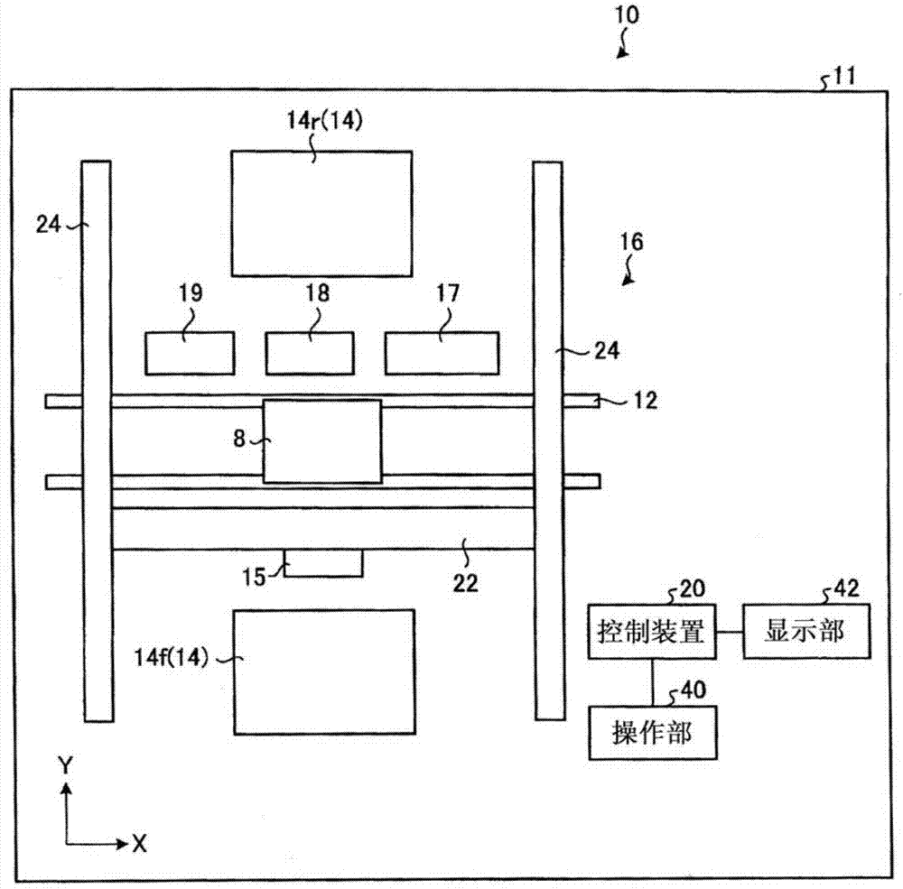
[0160]Hereinafter, embodiments of the electronic component mounting apparatus and electronic component mounting method according to the present invention will be described in detail based on the drawings. In addition, this invention is not limited by this embodiment. figure 1 It is a schematic diagram which shows the schematic structure of an electronic component mounting apparatus.

[0161] figure 1 ...


PUM


Abstract

The present invention discoses an electronic component installation apparatus and an electronic component installation method, and the lead type electronic component can be installed in high efficiency and precision. The electronic component installation apparatus utilizes a load head that moves on a plane transmit the electronic component to a oad position of a basepate, and has an electronic component supply unit that supplies the electronic component; a load head main body that has a nozzle, a nozzle drive part and a load head support body, wherein the nozzle holds the main body of the electronic component supplied by the electronic component supply unit, the nozzle drive part moves the nozzle up and down or drives the nozze rotate, and the load head support body supports the nozzle and the nozze drive part; and a contol part that controls the load head main body and the movement of the electronic component supply unit. The control part determines the condition of installing the electronic component onto the baseplate through the oad head main body based on the lead length of the lead type electronic component if the electronic component is a lead type electronic component of the lead that is inserted into a jack hole of the baseplate.

Description

technical field [0001] The invention relates to a method of using a suction nozzle to hold an electronic component and move it to a substrate [0002] An electronic component mounting device for mounting on top, and an electronic component mounting method. Background technique [0003] An electronic component mounting apparatus for mounting an electronic component on a substrate includes a mounting head having a suction nozzle, and the electronic component is held by the suction nozzle and mounted on the substrate. The electronic component mounting device moves the suction nozzle of the mounting head in a direction perpendicular to the surface of the substrate to absorb the components in the electronic component supply device, and then makes the mounting head face to face in a direction parallel to the surface of the substrate. After reaching the mounting position of the suctioned component, the suction nozzle of the mounting head moves in a direction perpendicular to the s...

Claims


Application Information

Patent Timeline
Patent Type & Authority Applications(China)
IPC IPC(8): H05K13/02H05K13/04
Inventor 儿玉裕介
Owner JUKI CORP
Why Eureka
Try Eureka