Tape dispenser

A dispenser and belt distribution technology, applied in the direction of thin material processing, metal processing equipment, sending objects, etc., can solve the problems of dirt, dust or other debris pollution

Inactive Publication Date: 2013-08-14
3M INNOVATIVE PROPERTIES CO
View PDF8 Cites 0 Cited by
  • Summary
  • Abstract
  • Description
  • Claims
  • Application Information

AI Technical Summary

Problems solved by technology

The uncovered side may become contaminated with dirt, dust or other debris

Method used


Image

  • Tape dispenser
  • Tape dispenser
  • Tape dispenser

Examples


Embodiment Construction

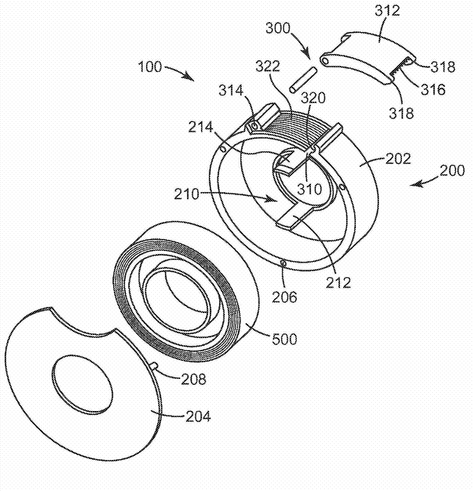
[0023] figure 1 is an exploded perspective view of an exemplary tape dispenser 100 for dispensing tape roll 500 . The tape dispenser 100 includes a tape reel housing 200 including a base 202 and a cover plate 204 and a tape dispensing mechanism 300 . In this embodiment, the reel housing 200 is circular to conform to the contours of the circular reel 500 contained therein. However, the shape of the reel housing 200 may be other shapes, sizes or configurations. In this embodiment, the base 202 has a plurality of attachment openings or holes 206 on its edges that engage attachment pegs 208 on the cover plate 204 to connect the cover plate 204 to the reel housing 200 . The base 202 may optionally include a tape core support. The tape core support 210 engages and supports the core of the tape roll 500 . like figure 1 As shown, the core support 210 includes a first interlock 212 and a second interlock 214 extending from the base 202 into the reel housing 200 . The first interl...


PUM


Abstract

A tape dispenser comprises a tape roll housing comprising a tape dispensing mechanism. The tape dispensing mechanism comprises a dispenser opening in the housing, a moving cover connected to the housing by a hinge, a cutting edge located at the outermost edge of the moving cover, a first landing surface defining the edge of the dispenser opening closest to the hinge, and a second landing surface located on the moving cover adjacent to the cutting edge. The landing surfaces are configured such the tape is formed into a cross-web concave shape between the first landing surface and the second landing surface.

Description

technical field [0001] The present invention relates to a tape dispenser having a cutting edge on a moving door. Background technique [0002] Conventional tape dispensers typically have a tape roll support for securing the core of the tape roll and side walls extending from the tape roll support to the cutting blade. These types of dispensers leave one side of the reel uncovered. This uncovered side may become contaminated with dirt, dust or other debris. [0003] A double-sided tape dispenser can be used to further accommodate tape rolls. A conventional double-sided tape dispenser, such as that shown in US Design Patent No. D510,951 (Carlson et al.), includes a second side wall for covering the tape roll. In order to open and gain access to the coil support, the side walls are usually twisted relative to each other. [0004] Tape dispensers capable of completely covering the tape in the dispenser are disclosed in US Patent No. 7,641,087 (Chang) and US Patent Applicatio...

Claims


Application Information

Patent Timeline
IPC IPC(8): B65H35/07B65H35/06
CPCB65H35/0026B65H35/0073B65H35/002Y10T225/282
Inventor 约耳·K·哈格隆德斯考特·D·皮尔森
Owner 3M INNOVATIVE PROPERTIES CO
Why Eureka
Try Eureka