

Planar patch antenna for substrate integration waveguide slotting coupled feeding
A substrate-integrated waveguide and patch antenna technology, applied in slot antennas, resonant antennas, circuits, etc., can solve problems such as inconvenient integration of microwave planar circuits, radiation loss, and patch radiation effects.
- Summary
- Abstract
- Description
- Claims
- Application Information
AI Technical Summary
Problems solved by technology
Method used
Image

Examples
Embodiment Construction
[0014] In order to make the purpose, technical solution and advantages of the present invention clearer, the present invention will be further described in detail below in conjunction with the accompanying drawings and embodiments.
[0015] It should be understood that the specific embodiments described here are only used to explain the present invention, not to limit the present invention.
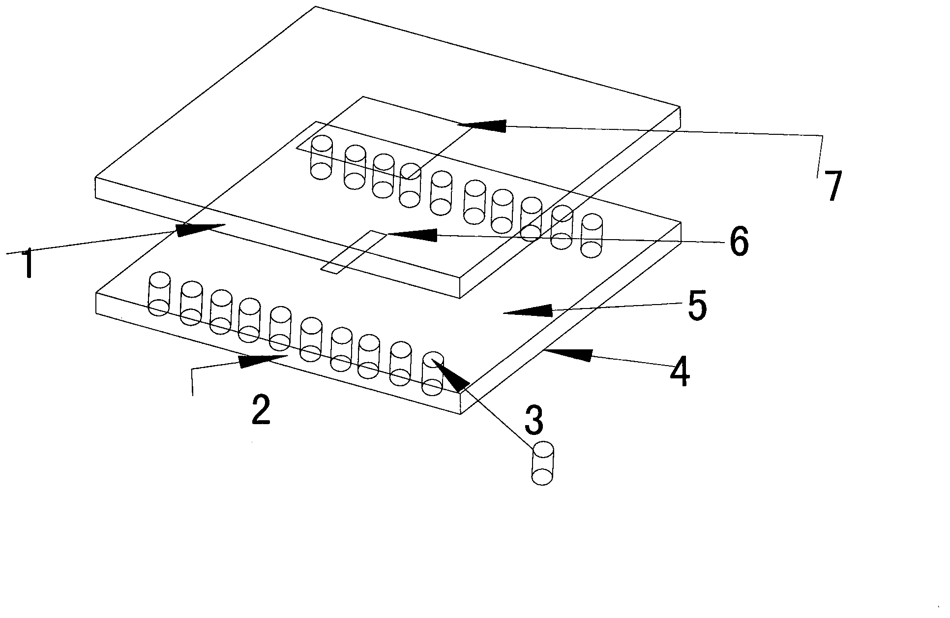
[0016] As shown in the figure, the embodiment of the present invention provides an antenna based on substrate integrated waveguide slot coupling feeding, which includes an upper substrate 1, a lower substrate 2, two rows of metallized via holes 3 located on the lower substrate, The metal plate 4 on the front side of the lower substrate, the metal plate 5 on the opposite side of the lower substrate, the gap 6 on the front metal plate, and the radiation patch 7 on the upper metal plate; the upper substrate 1 is superimposed on the lower substrate 2 .
[0017] In this embodiment, the lower s...
PUM
 Abstract
Description
Claims
Application Information