

Solar energy and wind energy non-interfering street lamp
A technology of solar energy and solar panels, applied in energy-saving lighting, lighting and heating equipment, outdoor lighting, etc., can solve the problems of battery panel power drop, affecting system use effect and lifespan, etc.
- Summary
- Abstract
- Description
- Claims
- Application Information
AI Technical Summary
Problems solved by technology
Method used
Image

Examples
Embodiment 1
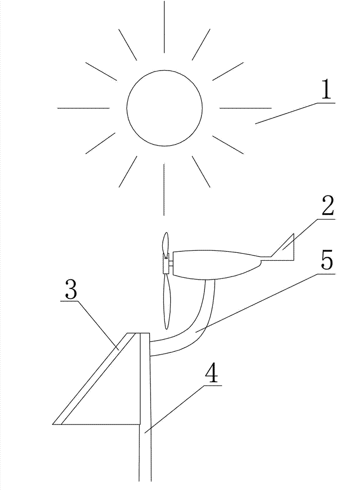
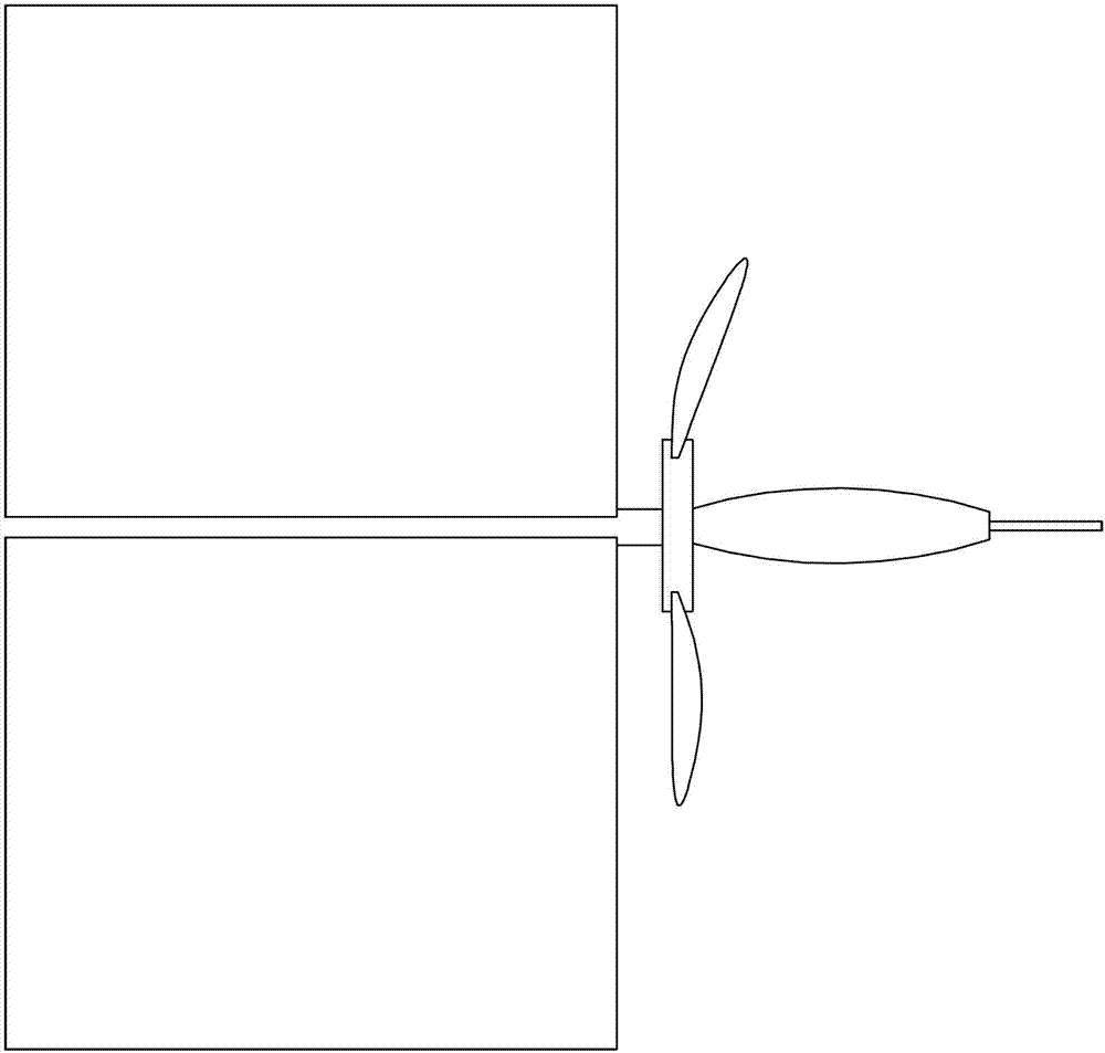
[0019] Depend on Figure 1 to Figure 6 It can be seen that the present invention includes a wind generator 2, a solar panel 3 and a light pole 4, and the wind power generator 2 is installed on the light pole 4 through a curved arm 5, so that when the sun shines, the wind power generator 2 leaves a shadow on the solar cell. on board 3, where:
[0020] The solar panel 3 is fixed on one side of the light pole 4 through the connecting piece 6, and the curved arm 5 is fixed on the light pole 4 and protrudes from the other side.
[0021] The wind generator 2 is fixed on the top of the curved arm 5 .
[0022] Structural principle of the present invention
[0023] like figure 1 As shown, the present invention is mainly composed of a wind generator 2, a solar panel 3, a light pole 4, and a curved arm 5. The solar battery panel 3 is installed on the light pole 4, and the light pole 4 is provided with a curved arm 5. The arm 5 is provided with a wind energy generator 2 , and the win...
Embodiment 2
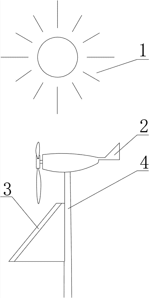
[0026] like Figure 7 to Figure 8 As shown, it is another embodiment of the present invention. The present invention includes a wind generator 2, a solar panel 3 and a lamp post 4, and the wind generator 2 is installed on the lamp post 4 through a straight rod 8, and the solar panel 3 One side of the light pole 4 protrudes outward through the bracket 7, avoiding the shadow of the wind power generator 2 on the solar panel 3 when the sun is shining, wherein:
[0027] The solar panel 3 is fixed on one side of the light pole 4 through the connecting piece 6, and the straight pole 8 is fixed on the light pole 4,
[0028] The wind energy generator 2 is fixed on the top of the straight rod 8 .
[0029] working principle
[0030] Extend the solar panel 3 through the support 7 within the shadow projection range of the wind generator 2, so that no matter which direction the sun is located, the wind generator will not leave a shadow on the solar panel, so that the solar panel can be us...
PUM
 Abstract
Description
Claims
Application Information