Die clamping mechanism of injection machine

A mold clamping mechanism and injection molding machine technology, applied in the field of mold clamping mechanism, can solve problems such as product quality reduction, enterprise economic loss, and product flashing

Inactive Publication Date: 2013-09-25
NINGBO JINGBAN IND
View PDF5 Cites 2 Cited by
  • Summary
  • Abstract
  • Description
  • Claims
  • Application Information

AI Technical Summary

Problems solved by technology

The deformation of the moving template will lead to defective products such as flashing in the p

Method used


Image

  • Die clamping mechanism of injection machine

Examples


Embodiment Construction

[0012] The present invention will be further described in detail below in conjunction with the accompanying drawings and embodiments.

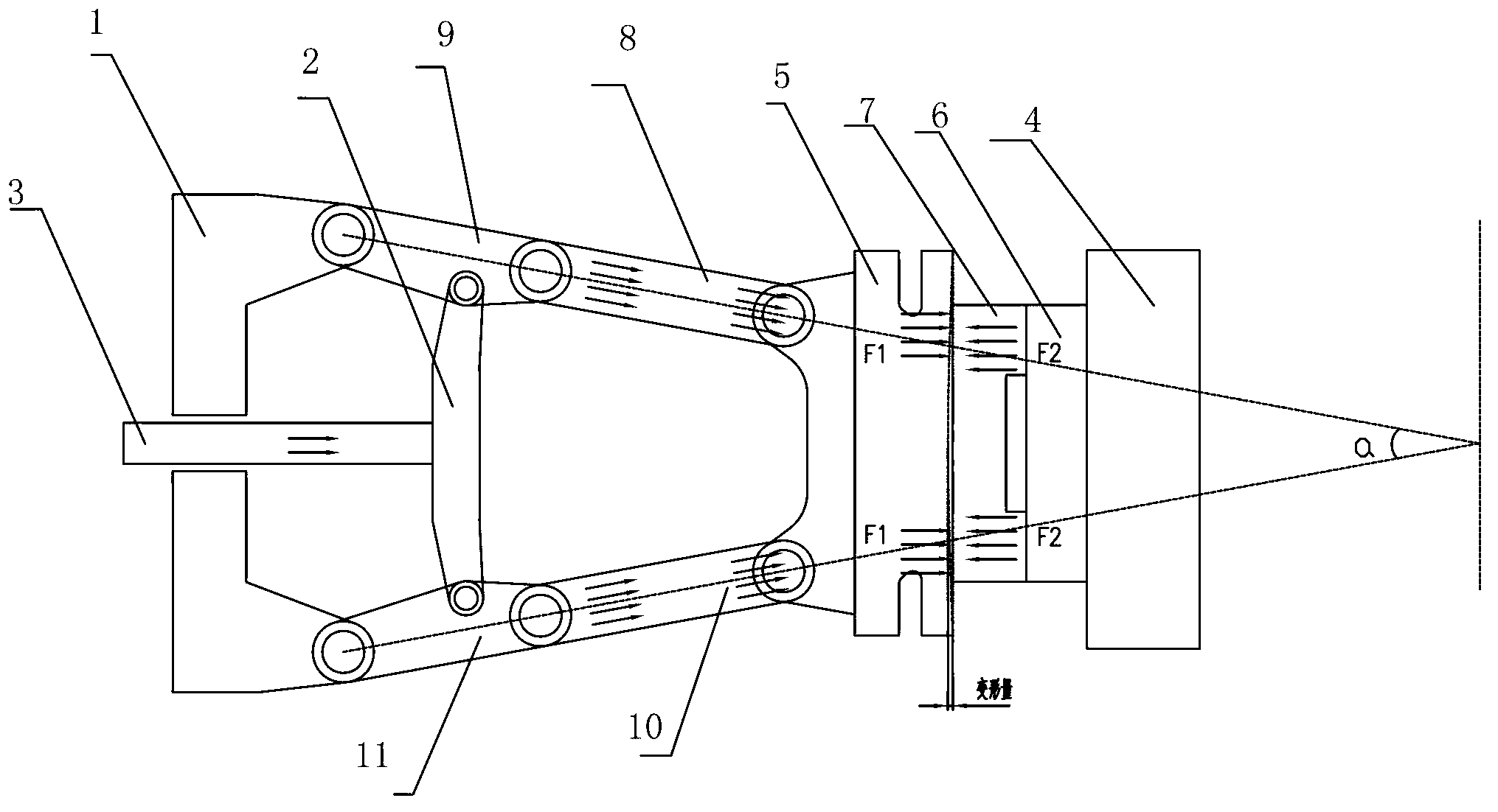
[0013] A mold clamping mechanism for an injection molding machine, comprising a rear platen 1, a connecting rod mechanism, a thrust seat 2, a mold locking piston rod 3, a fixed platen 4 and a movable platen 5, a fixed mold 6 is installed on the fixed platen 4, and a fixed platen 5 is mounted on the movable platen 5 The movable mold 7 is installed, the rear template 1 is connected with the fixed template 4 through the connecting rod mechanism, the thrust seat 2 is fixed with the connecting rod mechanism, the clamping piston rod 3 is fixed with the thrust seat 2, and the connecting rod mechanism includes symmetrically distributed first connecting rods assembly and the second link assembly, the first link assembly and the second link assembly have the same structure, when the fixed mold 6 and the movable mold 7 are locked, a 20 is formed between t...


PUM


Abstract

The invention discloses a die clamping mechanism of an injection machine. The die clamping mechanism comprises a back die plate, a link mechanism, a thrust block, a die clamping piston rod, a fixed die plate and a moving die plate. A fixed die is arranged on the fixed die plate. A moving die is arranged on the moving die plate. The back die plate is connected with the fixed die plate through the link mechanism. The thrust block and the link mechanism are fixed. The die clamping piston rod and the thrust block are fixed. The link mechanism comprises a first link assembly and a second link assembly which are in symmetric distribution. The first link assembly and the second link assembly have the same structure. When the fixed die and the moving die are clamped tightly, an angle of 20-25 degrees between the first link assembly and the second link assembly is formed. The die clamping mechanism is advantageous in that the upper and lower surfaces of the moving die plate bear force F1 coming from a front link rod, the center of the moving die plate bears the die-supporting force F2 coming from the moving die, because a V shape is formed by a back link and the front link, the generated force F1 is more concentrated, and after the generated F1 cancels out the central force F2, only little deformation is generated.

Description

technical field [0001] The invention relates to a mold clamping mechanism of an injection molding machine. Background technique [0002] The mold clamping mechanism of the traditional injection molding machine includes the clamping piston rod, the rear platen, the rear connecting rod and the thrust seat, the front connecting rod, the rear platen and the fixed platen are fixed respectively, the movable mold is fixed on the movable platen, and the fixed mold is fixed on the fixed platen , the rear connecting rod is fixed on the rear template, the front connecting rod is fixed on the moving template, the rear connecting rod is respectively connected with the thrust seat and the front connecting rod, and the clamping piston rod is connected with the thrust seat; when the mold is locked, the thrust of the clamping piston rod It is transmitted to the rear connecting rod through the thrust seat, and then to the movable template through the front connecting rod. The movable templat...

Claims


Application Information

Patent Timeline
IPC IPC(8): B29C45/68
Inventor 翁贞琼张志刚
Owner NINGBO JINGBAN IND
Why Eureka
Try Eureka