Dynamic braking device used for lifting device rotating pin mechanism

A technology of energy-consuming braking and spreaders, which is applied in the direction of AC motor deceleration device, electric motor/converter plug, etc., and can solve the problems of adding electric push rods and thread seizure

Inactive Publication Date: 2013-09-25
SHANGHAI ZHENHUA HEAVY IND +1
View PDF4 Cites 0 Cited by
  • Summary
  • Abstract
  • Description
  • Claims
  • Application Information

AI Technical Summary

Problems solved by technology

[0004] The purpose of this invention patent is to solve the problem that the electric push rod of the electric container spreader re-pin mechanism has no brake itself after power failure, and increase the braking force of the electric push rod from the electrical aspect, so that the lock head of the electric container spreader re-pin mechanism can be positioned More accurate, and at the same time avoid the problem that the inertial force of the electric push rod makes the thread of the screw rod and the thread of the motor rotor seized

Method used


Image

  • Dynamic braking device used for lifting device rotating pin mechanism
  • Dynamic braking device used for lifting device rotating pin mechanism
  • Dynamic braking device used for lifting device rotating pin mechanism

Examples


Embodiment Construction

[0029] The detailed features and advantages of the present invention are described in detail below in the specific embodiments, the content of which is sufficient to enable any person skilled in the art to understand the technical content of the present invention and implement it accordingly, and according to the specification, claims and drawings disclosed in this specification , those skilled in the art can easily understand the related objects and advantages of the present invention.

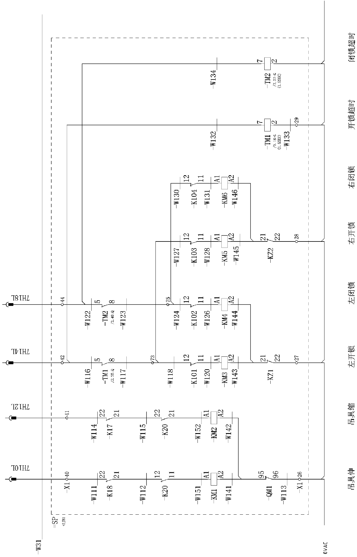
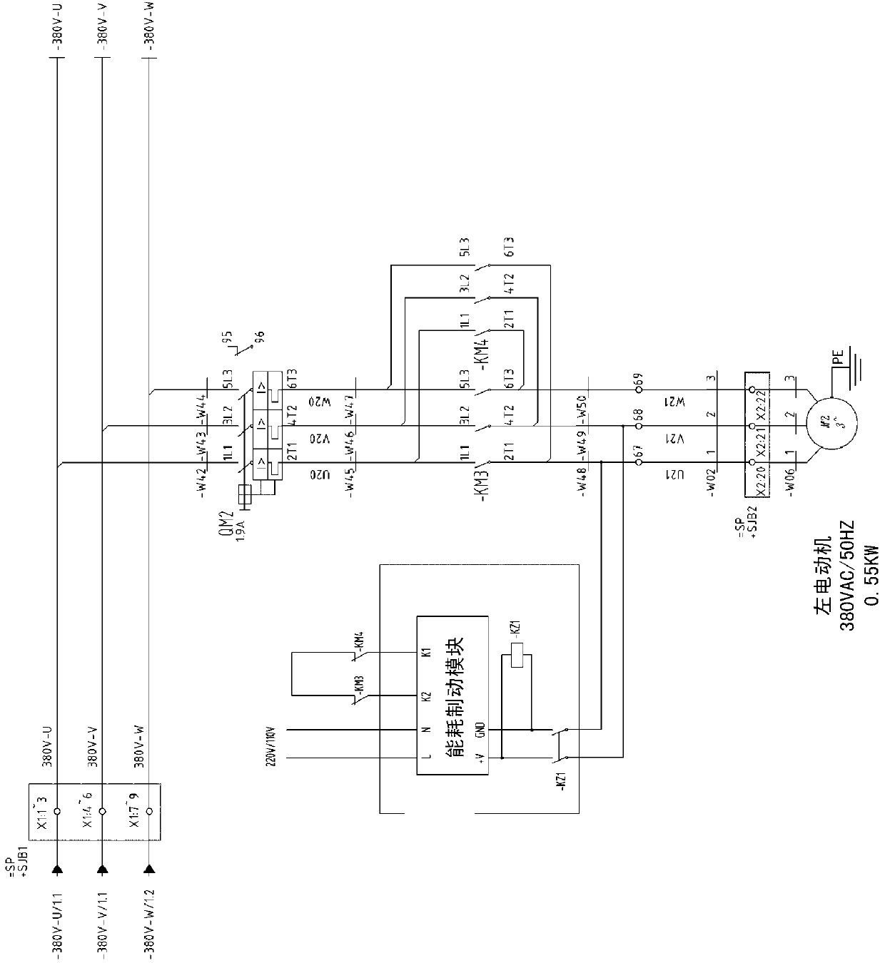
[0030] The repinning mechanism of the electric spreader is driven by the electric push rod. The working principle of the electric push rod is that the rotor of the motor rotates to drive the screw to move in a straight line, and the linearly moving screw drives the lock head of the spreader's repinning mechanism to open and close. However, the electric push rod itself has no braking system, and the inertial force of the electric push rod will cause the threads of the screw rod and the threads ...


PUM


Abstract

The invention provides a dynamic braking device used for a lifting device rotating pin mechanism. The dynamic braking device comprises a dynamic braking module and an isolating protection relay, wherein the dynamic braking module is provided with an input end, a triggering end and an output end, when a motor losses power, the triggering end is in breakover, the output end is triggered by the triggering end to output a pulse voltage, and the pulse voltage drivers the isolating protecting relay. The isolating protecting relay makes the pulse voltage connected to a stator winding of the motor, and therefore the stator winding can generate a stationary magnetic field, a rotor of the motor can rotate to generate induced electromotive force in the stationary magnetic field, and the current of the rotor and torque generated by the stationary magnetic field hinder the rotor from continually rotating.

Description

technical field [0001] The invention relates to a container crane, in particular to the braking technology of an electric push rod driving a reversing mechanism of a spreader. Background technique [0002] The repinning mechanism of the electric spreader is driven by the electric push rod. The working principle of the electric push rod is that the rotor of the motor rotates to drive the screw to move in a straight line, and the linearly moving screw drives the lock head of the spreader's repinning mechanism to open and close. The electric push rod has a simple structure, easy installation, and good shock and shock resistance, but the electric push rod itself has no braking system, and the inertial force of the electric push rod will cause the thread of the screw rod and the thread of the motor rotor to die. [0003] Therefore, there is an urgent need for a dynamic braking device that is used in the repinning mechanism of the spreader and enables the electric push rod to have...

Claims


Application Information

Patent Timeline
Patent Type & Authority Applications(China)
IPC IPC(8): H02P3/24
Inventor 金为民徐坤司苏来张茂
Owner SHANGHAI ZHENHUA HEAVY IND
Why Eureka
Try Eureka