Cold therapy apparatus using heat exchanger

A heat exchanger and heat technology, which is applied in the directions of heating devices for therapeutic treatment, cooling devices for therapeutic treatment, contraceptive devices, etc., can solve the problems of patient discomfort, thermal potential of consumption equipment, temperature control, etc.

Inactive Publication Date: 2013-10-02
BREG
View PDF9 Cites 12 Cited by
  • Summary
  • Abstract
  • Description
  • Claims
  • Application Information

AI Technical Summary

Problems solved by technology

[0003] Although known devices provide therapeutic cooling, these devices have certain drawbacks
For example, temperature control of some of these devices is difficult, leading to instances where the water is frozen to the point of discomfort for the patient
Also, certain devices cause the ice to melt too quickly, consuming the thermal potential of the device

Method used


Image

  • Cold therapy apparatus using heat exchanger
  • Cold therapy apparatus using heat exchanger
  • Cold therapy apparatus using heat exchanger

Examples


Embodiment Construction

[0032] flow state

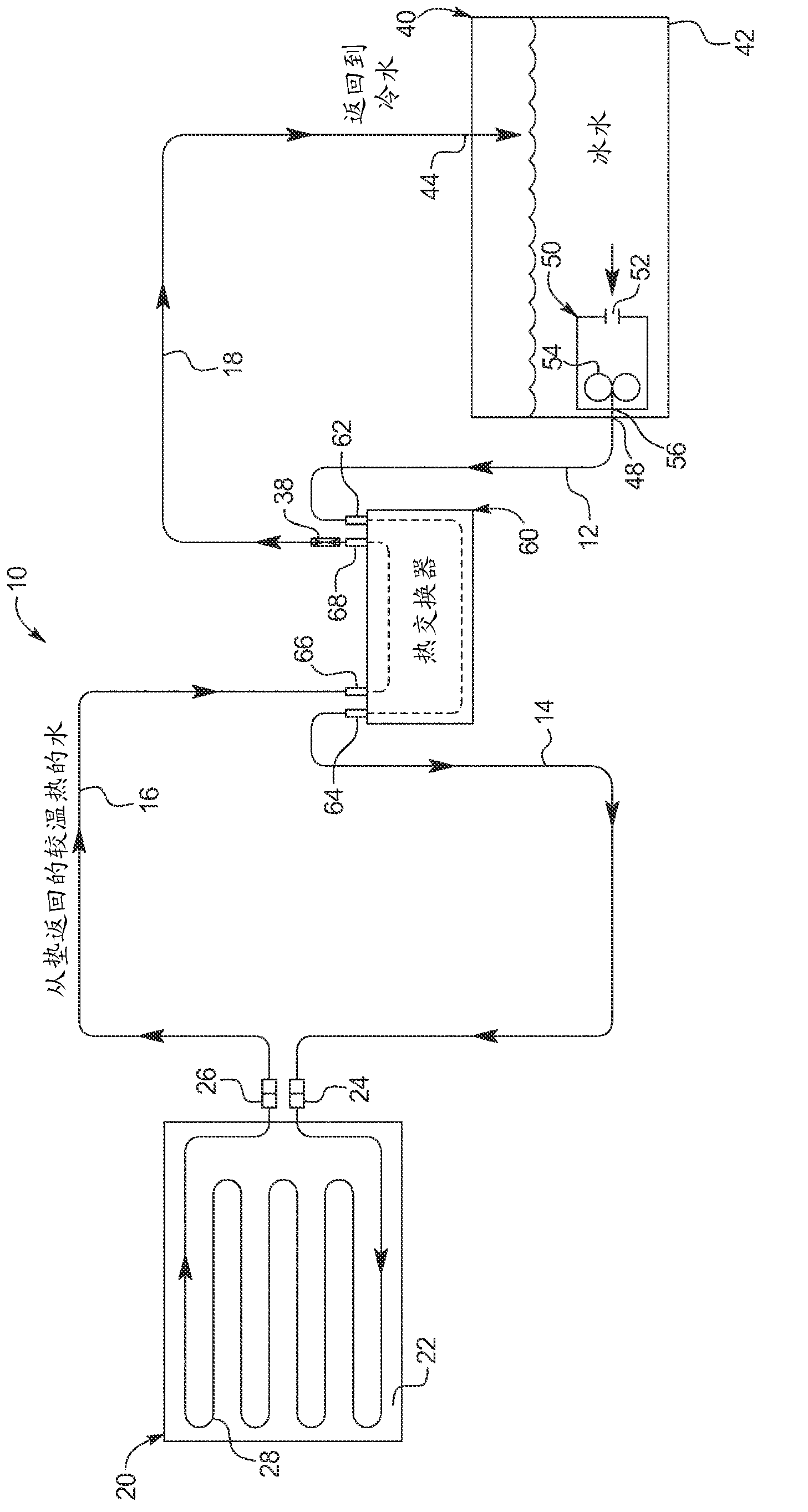
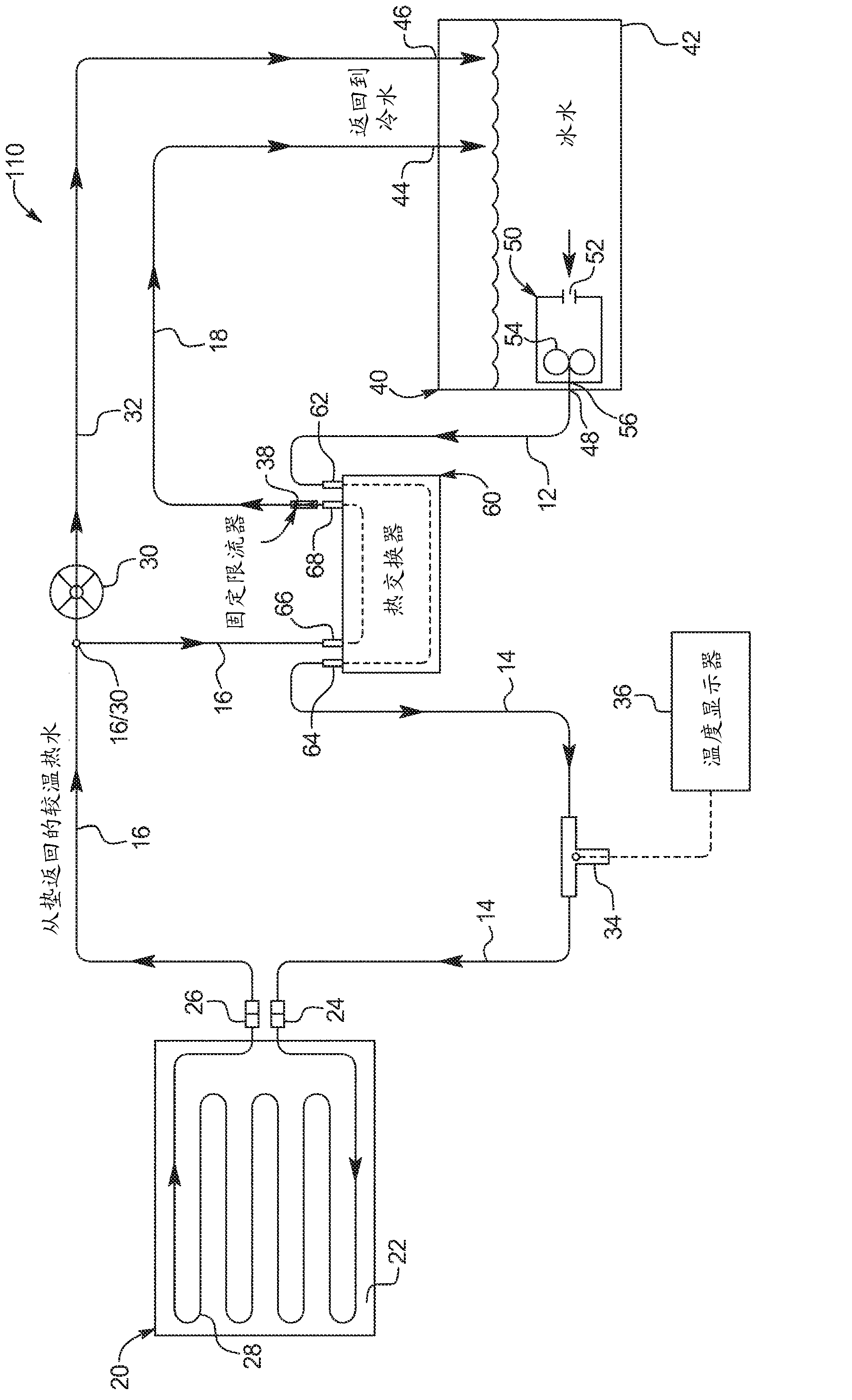
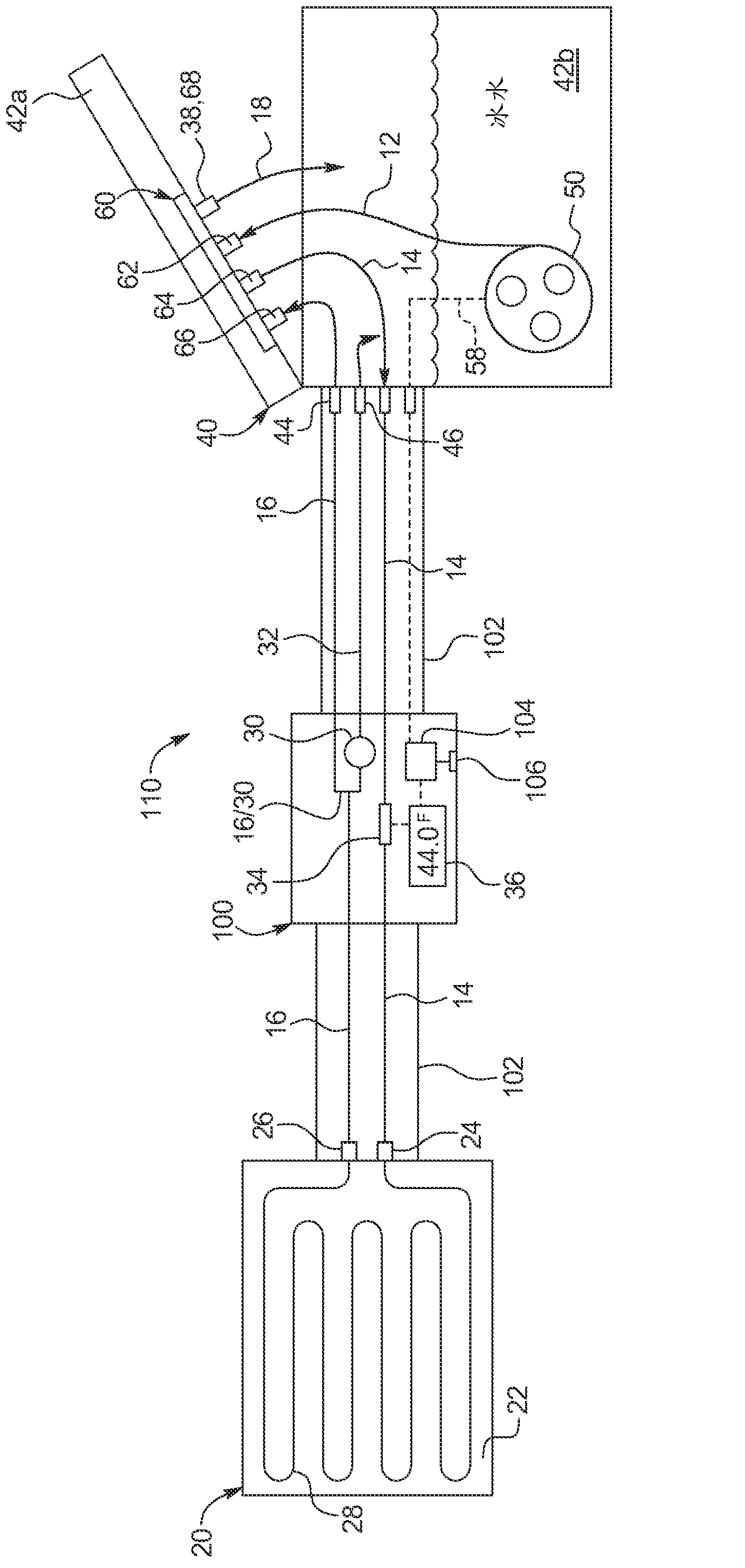
[0033] Reference is now made to the accompanying drawings, in particular figure 1 , an embodiment of the cold therapy system of the present invention is represented by system 10 . The main components of system 10 include treatment pad 20 , cooling bath 40 and heat exchanger 60 . Each of these devices will be described in detail below. A plurality of channels connect the treatment pad 20 , the cooling tank 40 and the heat exchanger 60 . For example, the cooling bath-pathway 12 extends from the cooling bath outlet 48 of the cooling bath 40 to the cooling water inlet 62 of the heat exchanger 60 . The exchanger-pad passage 14 extends from the cooling water outlet 64 of the heat exchanger 60 to the pad inlet connection 24 of the patient pad 20 . The pad-exchanger passage 16 extends from the pad outlet connection 26 to the hot water inlet 66 of the heat exchanger 60 . The exchanger-cooling tank passage 18 extends from the heated water outlet 68 of the heat...


PUM


Abstract

A cold therapy system includes a cooling bath; a therapy pad; a heat exchanger; a first pathway fluidly connecting the cooling bath to the heat exchanger; a second pathway fluidly connecting the heat exchanger to an inlet of the therapy pad; a third pathway fluidly connecting an outlet of the therapy pad to the heat exchanger; and a fourth pathway fluidly connecting an outlet of the heat exchanger to the cooling bath.

Description

technical field [0001] The present invention relates generally to orthopaedic surgery, and in particular to cooling or heating for the treatment of sore or injured body parts. Background technique [0002] Cooling water is known to cool and soothe wounds or injured body parts. For example, US Patent Nos. 5,241,951 and 5,330,519 describe cryotherapy devices using cooling water. The aforementioned patent requires a variable flow restrictor for temperature control. The more the flow restrictor restricts, the less water flows through the cooling pad, resulting in a warmer treatment pad. The less restrictive the flow restrictor, the more water flows through the cooling pad, resulting in a cooler pad temperature. [0003] Although known devices provide therapeutic cooling, these devices have certain drawbacks. For example, it is difficult to control the temperature of some of these devices, resulting in the water freezing to a level that is uncomfortable for the patient. Also...

Claims


Application Information

Patent Timeline
Patent Type & Authority Applications(China)
IPC IPC(8): A61F7/02
CPCA61F7/02A61F2007/0056A61F2007/0096A61F2007/0266
Inventor 加里·R·布莱德索
Owner BREG
Why Eureka
Try Eureka