
Image Focus Error Estimation

A focus error and image technology, applied in the field of autofocus optical system, can solve the problems of not being able to run real-time view, high cost, increasing the size and weight of the optical system, etc.

Inactive Publication Date: 2017-01-18
BOARD OF RGT THE UNIV OF TEXAS SYST
View PDF3 Cites 0 Cited by
  • Summary
  • Abstract
  • Description
  • Claims
  • Application Information

AI Technical Summary

Problems solved by technology

Although the phase detection method is faster, more accurate and estimates the defocus sign, it is expensive to implement because it requires special beam splitters, mirrors, prisms and sensors
Also, additional hardware increases the size and weight of the optical system
Also, this method does not work in "live view" mode (feature that allows the display of an optical system such as that of a digital camera to be used as a viewfinder)

Method used


Image

  • Image Focus Error Estimation
  • Image Focus Error Estimation
  • Image Focus Error Estimation

Examples


Embodiment Construction

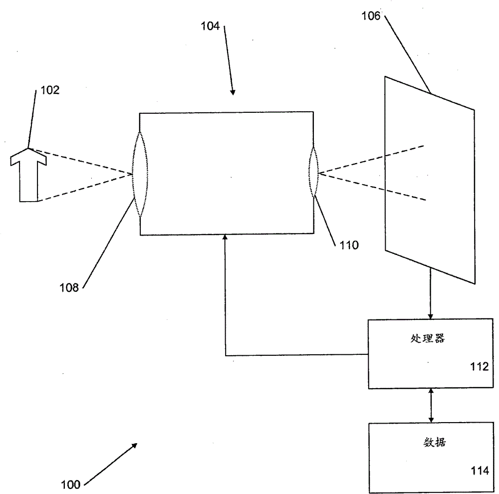
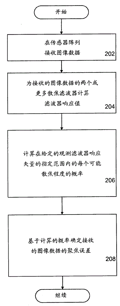
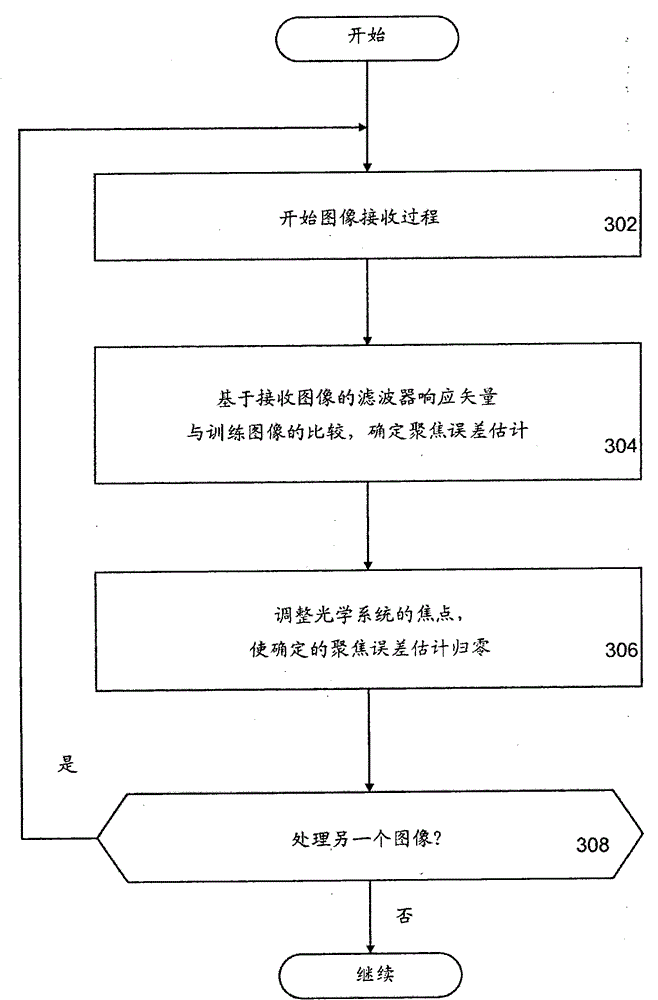
[0026] The present invention includes methods, systems and computer program products for estimating defocus (ie, focus error) within an image. In one embodiment of the invention, the optical system is characterized by a wave optics model of the point-spread function and the sensor array is characterized by the wavelength sensitivity, spatial sampling and noise functions of each sensor class. A training set of clear image patches is collected. A point-spread function is computed for each sensor class for each of the multiple degrees of defocus within the specified range. Additionally, a point-spread function for each degree of defocus is applied to each image patch, which is then sampled using the wavelength sensitivity and spatial sampling functions for each sensor within the sensor array. Noise is added to the sampled response of each sensor element of each sensor in the sensor array. Through a statistical learning step, the sensor responses from the sensor array are used t...


PUM


Abstract

Estimating the focus error in an image includes a training phase and an application phase. During the training phase, the optical system is represented by a point‑spread function. An image sensor array is represented by one or more wavelength sensitivity functions, one or more noise functions, and one or more spatial sampling functions. A point-spread function is applied to the image patches for each of the multiple degrees of defocus within a specified range to generate training data. Each image is sampled for each degree of defocus (ie focus error) using the wavelength sensitivity and spatial sampling functions. Add noise using the noise function. The responses from the sensor array to the training data are used to generate a defocus filter for estimating focus error within a specified range. A defocus filter is then applied to image patches of the training data, and the joint probability distribution of the filter responses for each degree of defocus is characterized. In the apply phase, the filter responses to arbitrary image blocks are obtained and combined to derive a continuous, signed estimate of the focus error for each arbitrary image block.

Description

[0001] Cross References to Related Applications [0002] This application is a co-pending non-provisional patent application with US Provisional Application No. 61 / 446566 filed on February 25, 2011, entitled "Defocus Estimation in a Single Natural Image". This provisional application is hereby expressly incorporated by reference in its entirety for all purposes. [0003] Statement Concerning Rights to Inventions Made in Federally Sponsored Research or Scientific Research [0004] The United States Government may have certain rights in this invention under the terms of National Institutes of Health Grant No. 2R01EY11747. technical field [0005] The present invention relates to autofocus optical systems, and more particularly to the estimation of errors in images received by the optical system. Background technique [0006] Autofocus optical systems (eg, digital still cameras, digital cameras, microscopes, microfabrication equipment) use sensors, control systems, and motors...

Claims


Application Information

Patent Timeline
Patent Type & Authority Patents(China)
IPC IPC(8): H04N5/232G02B7/36
CPCG02B7/36H04N23/672H04N23/673H04N23/70
Inventor W·吉斯勒J·伯格
Owner BOARD OF RGT THE UNIV OF TEXAS SYST
Learn More