Writing desk
A technology for writing desks and hinged seats, applied in the field of writing desks, can solve problems such as discomfort and inability to adapt to different people
- Summary
- Abstract
- Description
- Claims
- Application Information
AI Technical Summary
Problems solved by technology
Method used
Image

Examples
Embodiment Construction
[0009] The present invention will be further described in detail below in conjunction with the accompanying drawings and specific embodiments.
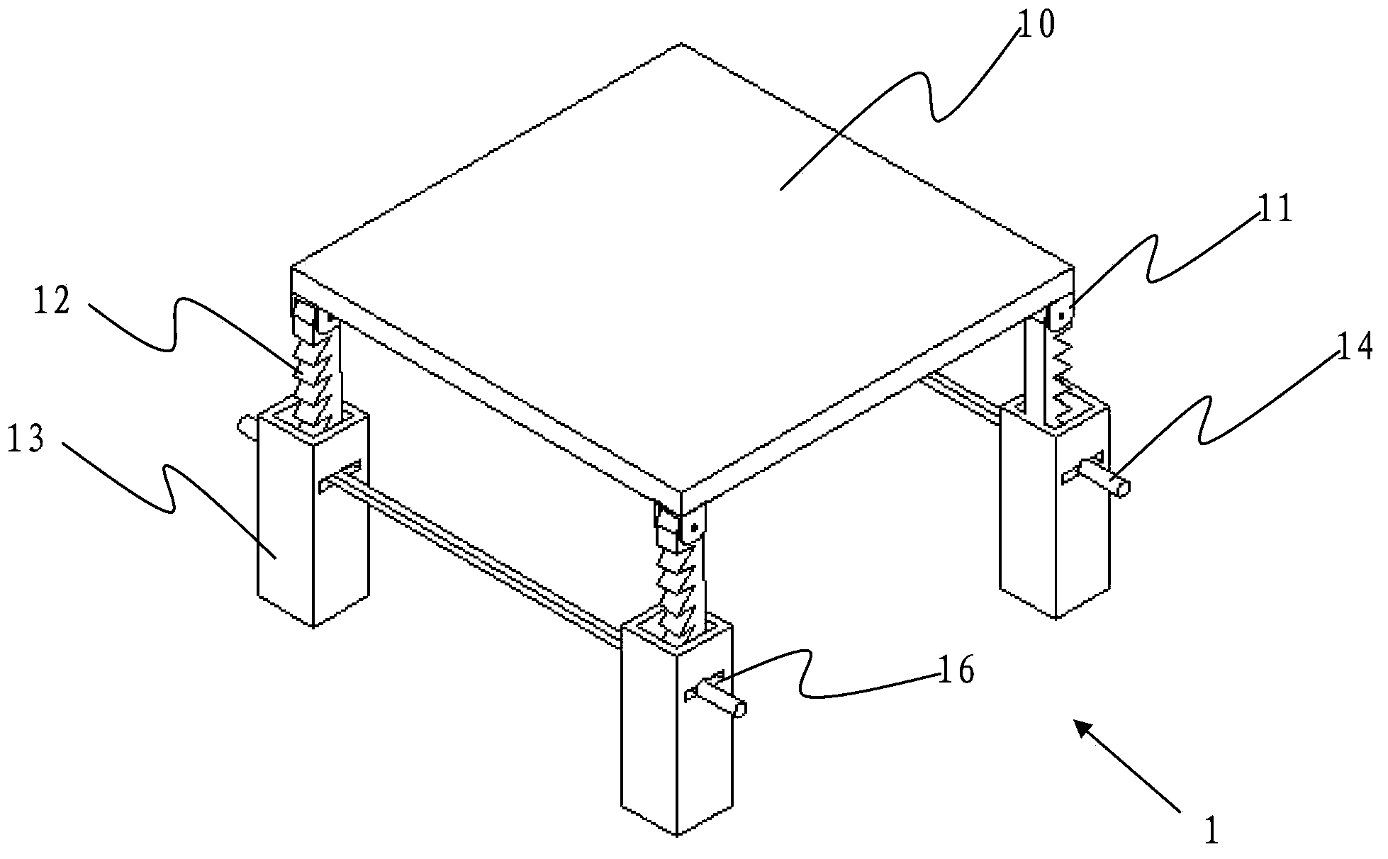
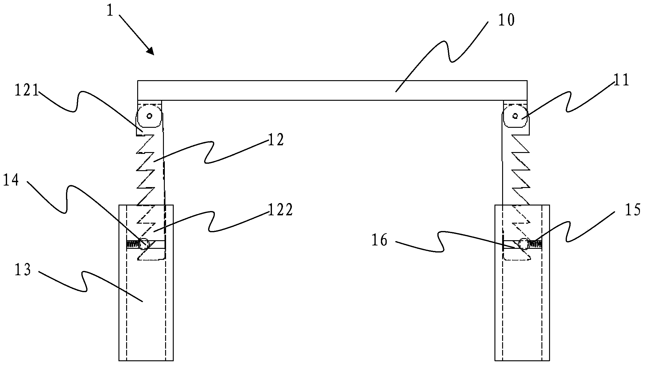
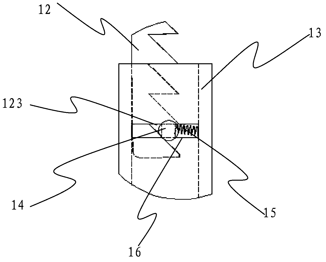
[0010] refer to figure 1 As shown, the writing desk 1 of the present invention includes a desktop 10, the four corners of the bottom of the desktop 10 are respectively provided with a pivot seat 11, and a toothed downward rack 12 is pivotally provided on the pivot seat 11. figure 2 As shown, the first end 121 of the rack 12 is pivotally connected to the pivot seat 11, the second end 122 of the rack 12 is inserted into a hollow column 13, and a cross bar 14 is inserted in the middle of the hollow column 13. For the convenience of operation, you can A crossbar 14 is respectively arranged on both sides of the writing desk 1, and the two ends of the crossbar 14 respectively pass through the corresponding two hollow columns 13, see further image 3 As shown, one side of the cross bar 14 is against the toothed lower surface 123 of the rac...
PUM
 Abstract
Description
Claims
Application Information