Eureka AIR delivers breakthrough ideas for toughest innovation challenges, trusted by R&D personnel around the world.

A projectile monocular video pose measurement method and target pattern

A pose measurement and projectile technology, which is applied in the field of monocular video pose measurement of projectiles, can solve the problem that the plane target cannot adapt to the surface structure of the projectile, and achieve the effect of simple structure, large measurement range and wide application range

Active Publication Date: 2016-11-30
BEIJING INSTITUTE OF TECHNOLOGYGY +1
View PDF4 Cites 0 Cited by
  • Summary
  • Abstract
  • Description
  • Claims
  • Application Information

AI Technical Summary

Problems solved by technology

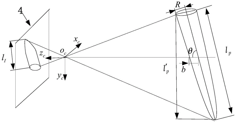
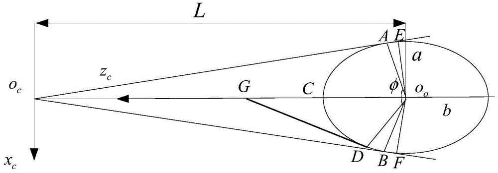
[0007] In order to solve the problem that the existing planar target cannot adapt to the curved surface structure of the projectile, and to improve the measurement accuracy of the projectile's pose, the purpose of the present invention is to design a target pattern on the surface of the projectile, and the target pattern has four in the field of view of the camera. The above coplanar feature points, and the corresponding projectile monocular video pose measurement method is proposed

Method used


Image

  • A projectile monocular video pose measurement method and target pattern
  • A projectile monocular video pose measurement method and target pattern
  • A projectile monocular video pose measurement method and target pattern

Examples


Embodiment Construction

[0040] The technical solution of the target pattern of the projectile and the monocular video pose measurement method of the projectile according to the present invention will be described in detail below with reference to the accompanying drawings and a typical embodiment.

[0041] see Figure 6, shown in 7 and 8, a target pattern of a projectile is designed as a band-shaped area around the outer circumferential surface of the projectile, and the target pattern is equally divided into 6 sub-regions 5 along the direction of the projectile axis; the adjacent sub-regions The color interval of is set to two colors, and the two colors have obvious contrast with the surface color of the projectile. The target pattern is located on the outer surface of the projectile, and is set as far as possible on the part with a larger diameter in the cross section of the projectile.

[0042] The six sub-regions 5 of the projectile are respectively set to two other colors that have a clear cont...


PUM


Abstract

The invention relates to a target pattern for projectiles and a monocular video pose measurement method using the pattern. The target pattern is a band-shaped area surrounding the outer circumferential surface of the projectile, which is equally divided into 6 sub-areas set at color intervals along the direction of the projectile axis, and a coding area is set inside the sub-areas, and the 4 vertices of each sub-area are used as feature points. Applying this target pattern for pose measurement should keep the projectile in the camera's field of view. Set a unique three-digit binary code for each sub-region. The sub-region is identified according to the code, and then the feature point is identified according to the position of the feature point on the sub-region. When solving the pose of the projectile, first determine the image coordinates of the feature points from the image of the camera, and then combine the coordinate values ​​of the corresponding feature points in the projectile coordinate system, transform the coordinate system and establish a system of equations, and jointly solve to obtain the position of the projectile posture. The method of the invention is simple and has a wide application range.

Description

technical field [0001] The invention relates to a projectile target pattern for a flying target and a monocular video pose measurement method for a projectile using the projectile target pattern. Background technique [0002] During the development and testing of projectiles, it is often necessary to obtain the pose parameters of the projectile, such as the landing attitude of the projectile. However, there is usually no precise pose measurement equipment installed on the projectile, so the pose measurement of the projectile becomes a difficult problem. [0003] Yu Qifeng et al.'s "Central Axis Method for Determining Pitch and Yaw Angles of Space Targets Using Optical Measuring Images" (Journal of National University of Defense Technology, 2000, Volume 22 (2): 15-19), proposed the central axis method, This method first uses the projectile contour features to fit the projectile's central axis equation, and then calculates the projectile's pitch angle and yaw angle according ...

Claims


Application Information

Patent Timeline
Patent Type & Authority Patents(China)
IPC IPC(8): G01C11/36
Inventor 谌德荣李蒙王长元宫久路周广铭蒋玉萍高翔霄杨晓乐
Owner BEIJING INSTITUTE OF TECHNOLOGYGY
Why Eureka
Eureka Blog
Learn More