Electronic device

A technology for electronic equipment and terminals, applied in circuits, electrical components, coupling devices, etc., to solve problems such as wear and deterioration

Inactive Publication Date: 2014-01-15
BUFFALO CORP LTD
View PDF6 Cites 2 Cited by
  • Summary
  • Abstract
  • Description
  • Claims
  • Application Information

AI Technical Summary

Problems solved by technology

[0011] However, as mentioned above, when a plug such as a USB is connected to a computer, etc., it needs to be inserted into a socket, etc., a...

Method used


Image

  • Electronic device
  • Electronic device
  • Electronic device

Examples


Embodiment Construction

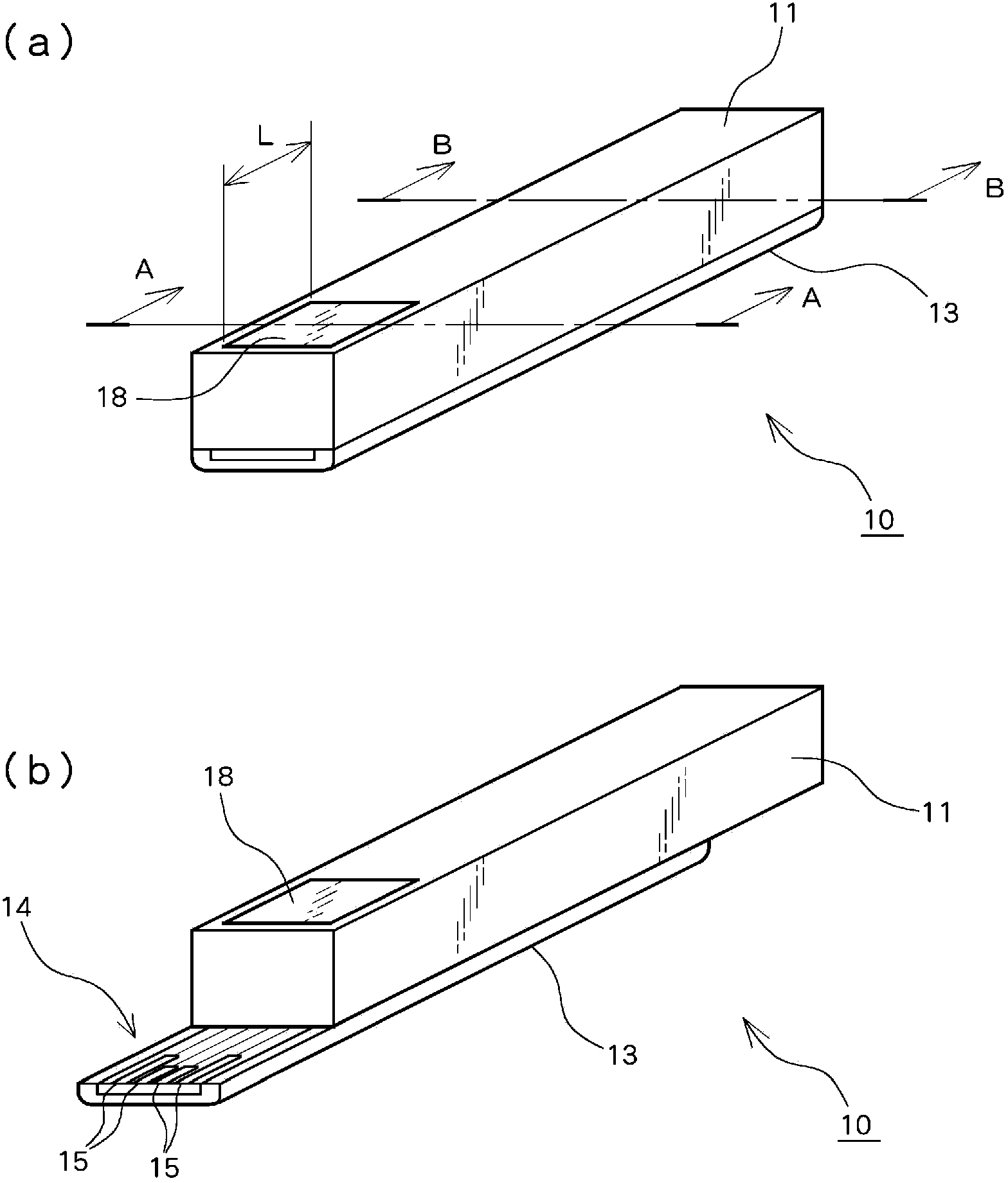
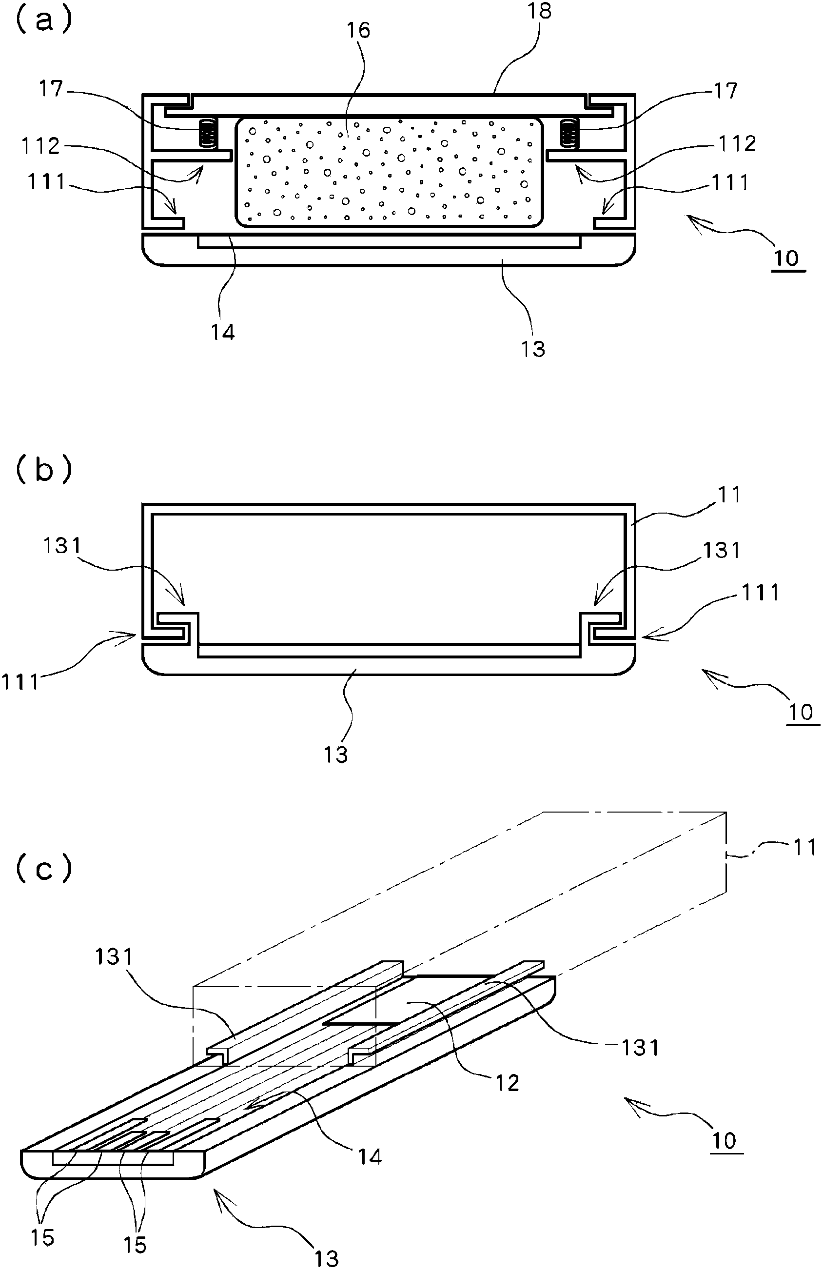
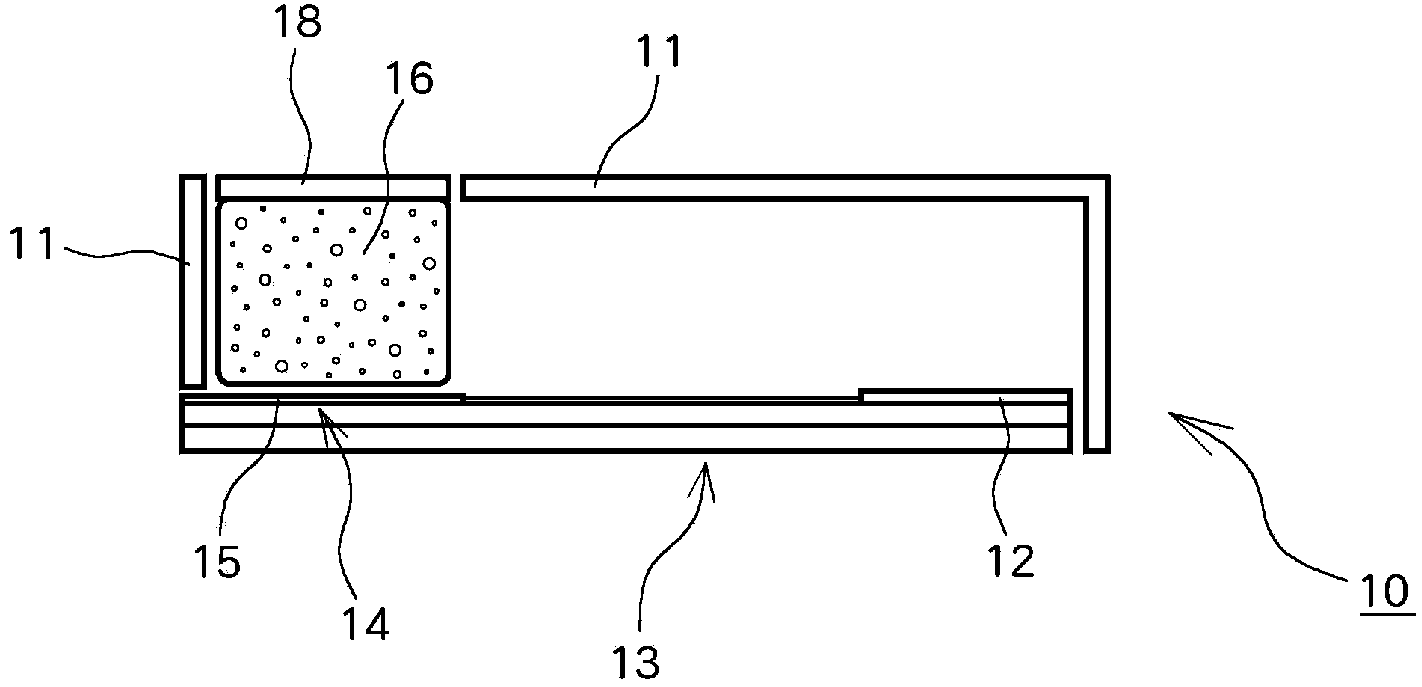
[0029] Embodiments of the present invention will be described with reference to the drawings. The electronic device according to the first embodiment of the present invention is, for example, figure 1 The illustrated USB memory 10 is implemented. As an example of the electronic device of this embodiment, the USB memory 10 is, for example, figure 1 As illustrated, a main body cover portion 11 as a cover member, a terminal member 13 , a terminal portion 14 , and a conductor pattern 15 are included.

[0030] The main body cover portion 11 has a substantially rectangular parallelepiped shape. However, from the viewpoint of design and the like, it may be a substantially parallelogram when viewed from the side. In the electronic device of this embodiment, the terminal member 13 has a terminal portion 14 at least on one end side, and the terminal portion 14 can be accommodated in the main body cover portion 11 as a cover member ( figure 1 (a)) and the position exposed to the o...


PUM


Abstract

The invention provides an electronic device, and a user can select whether to clean a terminal for connection or not. The electronic device comprises a cover component, a terminal component, and a terminal cleaning component. The terminal component is provided with a terminal portion on an end, and the terminal portion can move between a position contained in the cover component and a position exposed outside the cover component. The terminal cleaning component is configured on a side of the cover component, and can move between a position contacting the terminal and a position of retreating on a moving path of the terminal portion.

Description

technical field [0001] The present invention relates to an electronic device having, for example, a USB (Universal Serial Bus) connector or the like, connected to a computer and used. Background technique [0002] In recent years, various connectors have been used for connecting peripheral devices to personal computers and the like. For example, the USB (Universal Serial Bus) standard, which is a serial interface standard, is also used for connection with devices such as SSDs (Solid State Drives) that require relatively high data transfer speeds. [0003] Figure 10 It is a perspective view of a widely used so-called USB memory as an example of a device having the USB connector. The USB memory 200 includes a main body 202 that accommodates a memory as an information storage medium and a flat terminal 203 , the terminal 203 having a substantially rectangular top surface. In addition, conductor patterns 204 as a plurality of terminals are formed on at least one of the top su...

Claims


Application Information

Patent Timeline
IPC IPC(8): H01R13/502
Inventor 丸山裕
Owner BUFFALO CORP LTD
Why Eureka
Try Eureka