Roll-feed printing machine

A printing press and reel technology, applied in printing presses, rotary presses, printing, etc., can solve the problems of large building height and impossible integration, and achieve the effect of reducing the building height

Active Publication Date: 2014-01-22
MANROLAND WEB SYST
View PDF11 Cites 3 Cited by
  • Summary
  • Abstract
  • Description
  • Claims
  • Application Information

AI Technical Summary

Problems solved by technology

This results in a relatively large building height for the web-fed printing press, making it impossible to integrate the web-fed printing press into the printing hall at a low height

Method used


Image

  • Roll-feed printing machine
  • Roll-feed printing machine
  • Roll-feed printing machine

Examples


Embodiment Construction

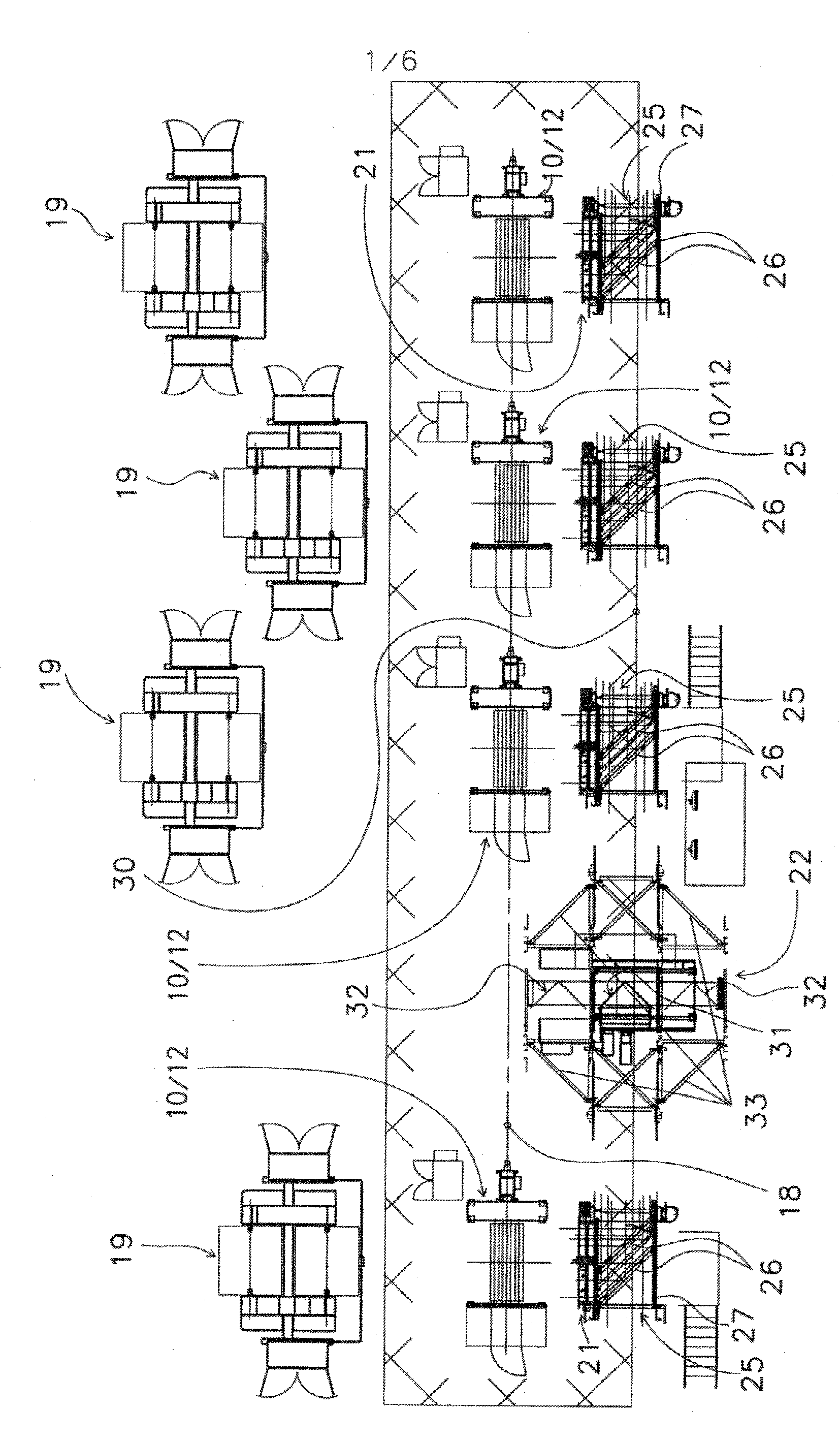
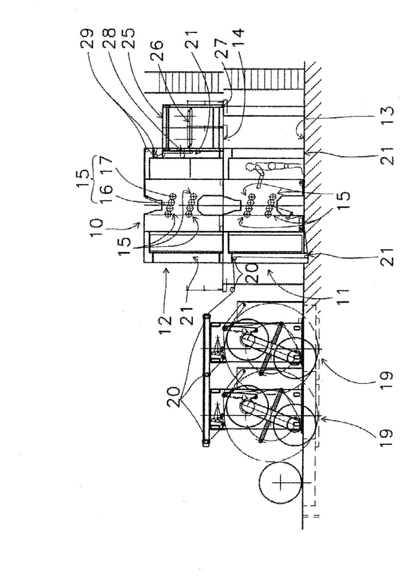
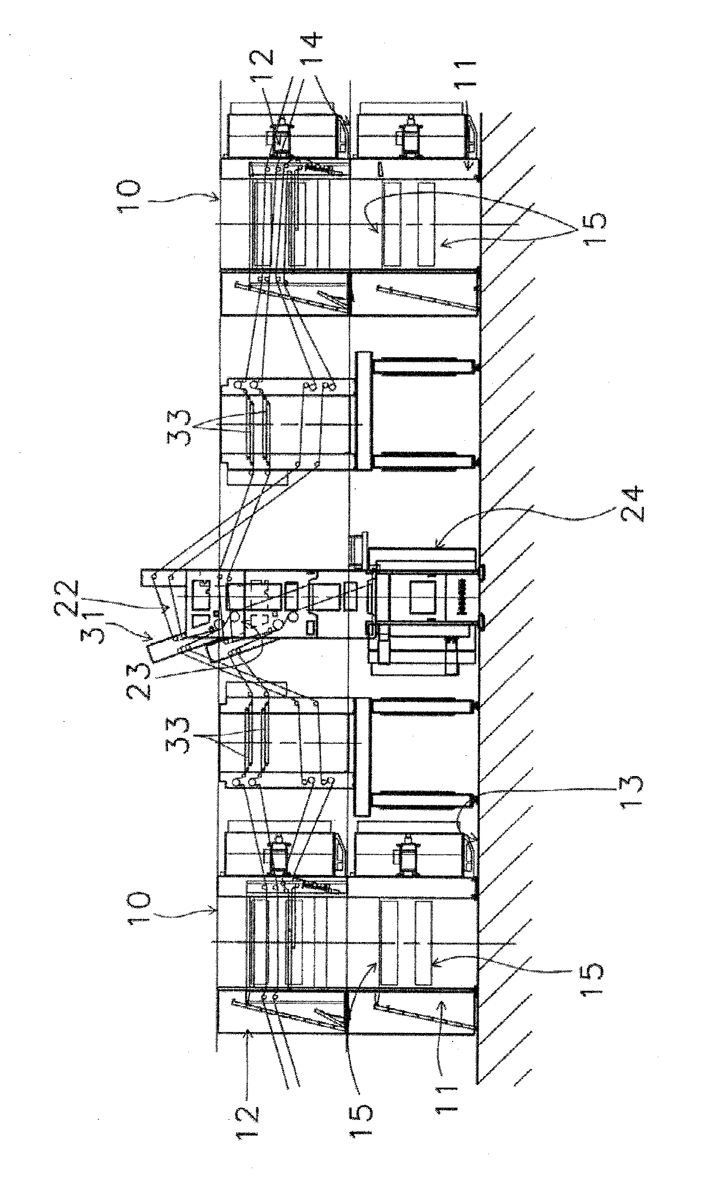
[0046] Figure 1-3 Different views of a web-fed printing press designed as a newspaper printing press according to the invention are shown, wherein in the exemplary embodiment shown the web-fed printing press as a whole comprises two printing units 11 , 12 The four printing towers 10, the two printing units 11, 12 are each vertically positioned to overlap each other.

[0047] The first printing unit 11 located on the lower side of each printing tower 10 is as from figure 2 and 3 It is most clearly positioned on the printing hall floor 13 and can be operated from the printing hall floor 13 by an operator. The upper second printing unit 12 of each printing tower 10 is positioned vertically above the first printing unit 11 of the corresponding printing tower 10 and can be operated based on a platform 14 formed above the printing hall floor 13 .

[0048] In the exemplary embodiment shown, the printing units 11 , 12 of each printing tower 10 are implemented as so-called eight-c...


PUM


Abstract

The printing machine has printing tower (10) that is assigned with a splicer (19), a web guide and reversal unit (25). A reversal unit is positioned laterally beside the second printing unit (12) of the respective printing tower, so that the second printing unit and reversal unit of the respective printing tower are operable by gallery plane. Each printing unit of the printing tower has a web guide frame (21) on both sides.

Description

technical field [0001] The invention relates to a web-fed printing machine according to the preamble of claim 1 . Background technique [0002] A web-fed printing press, in particular a web-fed printing press designed as a newspaper printing press, generally comprises one or more printing towers, wherein each printing tower comprises a plurality of printing units, the plurality of printing units Consists of multiple printed coupling groups positioned vertically on top of each other. Thus, each printing unit of each printing tower of a web-fed printing press designed as a newspaper printing press typically comprises four printing couples. The first printing unit located on the underside of each printing tower can be operated from the printing hall floor by the operator, that is, the printer, wherein the second printing unit of the corresponding printing tower vertically positioned above the first printing unit can be positioned and A gallery level formed above the floor of ...

Claims


Application Information

Patent Timeline
Patent Type & Authority Applications(China)
IPC IPC(8): B41F13/06B41F13/03B41F13/58
CPCB41F13/03B41F13/58B41F13/06B41F7/12B41F13/0024B41F13/02B41F13/54B65H19/1805B65H2301/41704B65H2801/21
Inventor S.菲舍尔M.维尔姆特B.特格
Owner MANROLAND WEB SYST
Why Eureka
Try Eureka