Manufacturing method for zigzag shafting alignment tool

A production method and bending shaft technology, applied in the direction of measuring devices, mechanical devices, mechanical measuring devices, etc., can solve the problems of inability to measure the offset and twist of the object, the value cannot be monitored and controlled, and the measured value is inaccurate. , to achieve intuitive measurement results, simple construction, and high measurement accuracy

Active Publication Date: 2014-01-29
WUCHANG SHIPBUILDING IND
View PDF5 Cites 10 Cited by
  • Summary
  • Abstract
  • Description
  • Claims
  • Application Information

AI Technical Summary

Problems solved by technology

Although this type of angle ruler can accurately measure the size of the angle between two object planes, due to the limitation of the measurement principle, it is impossible to measure the offset and twist of the measured object
Some specific tasks, such as: the alignment of the zigzag shaft system, etc., need to measure the plane angle, offset and twist between two objects at the same time, the general angle ruler can only roughly measure the angle, offset The quantity can only be estimated in advance. During calibration, the measured values ​​of the knuckle angle and offset of the input and output shafts are inaccurate, and the values ​​cannot be monitored and adjusted. After calibration with such a process method, shafting vibration and bearing heating often occur , abnormal noise and other unforeseen failures
At present, there is no tool that can accurately measure both the knuckle angle of the shaft and the offset of the shaft

Method used


Image

  • Manufacturing method for zigzag shafting alignment tool
  • Manufacturing method for zigzag shafting alignment tool
  • Manufacturing method for zigzag shafting alignment tool

Examples


Embodiment Construction

[0033] The present invention will be further described in detail below in conjunction with the accompanying drawings and specific embodiments.

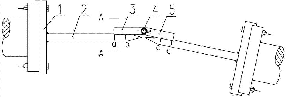
[0034] see figure 1 As shown, the embodiment of the present invention provides a method for manufacturing a zigzag shaft alignment tool, which includes the following steps:

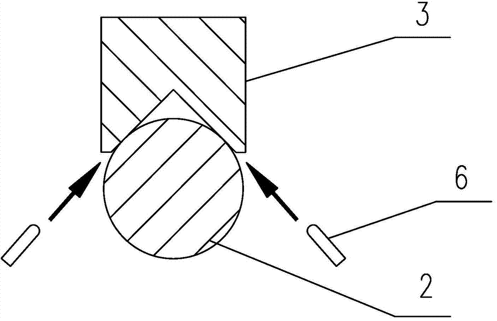
[0035] According to the number of zigzag inflection points designed on the zigzag shaft system, make a pair of calibration pointers between the adjacent input shafts and output shafts with a certain angle, see image 3 , Figure 4 As shown, each calibration pointer is a mechanical component welded by a flange 1 and a straight steel rod 2 with a tapered needle point. The straight steel rod 2 is concentric with the outer circle of the axially outer surface of the flange 1, and the two end faces of the flange 1 should be perpendicular to the axially outer surface of the straight steel rod 2. The outer diameter of the flange 1 and the graduation of the connecting s...


PUM

PropertyMeasurementUnit
verticalityaaaaaaaaaa

Abstract

The invention discloses a manufacturing method for a zigzag shafting alignment tool, and relates to the field of alignment of zigzag shafting. The manufacturing method includes respectively manufacturing a pair of alignment pointers between an input shaft and an output shaft, wherein the input shaft and the output shaft are adjacent and an included angle is formed between the both, and each alignment pointer is a mechanical member formed by welding of a flange and a straight steel bar with a tapered tip; manufacturing a set of alignment right-angle ruler comprising a first right-angle ruler arm, an angle indicating bolt and a second right-angle ruler arm, wherein a screw hole is formed at the ruler arm end of each of the first right-angle ruler arm and the second right-angle ruler arm, the angle indicating bolt penetrates the screw hole to fix the first right-angle ruler arm and the second right-angle ruler arm together, and the first right-angle ruler arm and the second right-angle ruler arm rotate around the angle indicating bolt which displays included angle between the first right-angle ruler arm and the second right-angle ruler arm. By the method, both angle and offset can be measured, measuring results are visual, measuring accuracy is high, construction is simple and convenient, the tool is convenient to demount, and production efficiency can be improved.

Description

technical field [0001] The invention relates to the field of zigzag shaft alignment, in particular to a manufacturing method of zigzag shaft alignment tooling. Background technique [0002] In mechanical engineering and marine engineering power transmission shafting, digital display angle rulers and universal angle rulers are often used. The measurement principle of this type of angle ruler is to use one side of the angle ruler as a reference, and temporarily set it at a certain angle. Fix on one of the two measuring objects that need to measure the angle, use the sensor installed on the other side of the angle ruler or the rotating mechanism to measure the position and displacement of the other measuring object, and obtain the angle between the two size. Although this type of angle ruler can accurately measure the angle between two object planes, due to the limitation of the measurement principle, it is impossible to measure the offset and twist of the measured object. So...

Claims


Application Information

Patent Timeline
Patent Type & Authority Applications(China)
IPC IPC(8): G01B5/24G01B5/02B23P15/00
Inventor 许克文秦启虎胡社来
Owner WUCHANG SHIPBUILDING IND
Why Eureka
Try Eureka