Manufacturing method of light guide plate

A manufacturing method and technology of light guide plates, applied in optics, light guides, optical components, etc., can solve the problems of increasing time and cost, achieve good manufacturing accuracy, save product development time, and save product development time and cost.

Inactive Publication Date: 2017-02-01
NANO PRECISION TAIWAN LTD
View PDF9 Cites 2 Cited by
  • Summary
  • Abstract
  • Description
  • Claims
  • Application Information

AI Technical Summary

Problems solved by technology

However, when the design of the optical microstructure is changed or needs to be adjusted, the injection molding mold must be remade, which greatly increases the time and cost of product development.

Method used


Image

  • Manufacturing method of light guide plate
  • Manufacturing method of light guide plate
  • Manufacturing method of light guide plate

Examples


Embodiment Construction

[0025] The foregoing and other technical contents, features and effects of the present invention will be clearly presented in the following detailed description of a preferred embodiment with reference to the accompanying drawings. The directional terms mentioned in the following embodiments, such as: up, down, left, right, front or back, etc., are only referring to the directions of the drawings. Accordingly, the directional terms are used to illustrate and not to limit the invention.

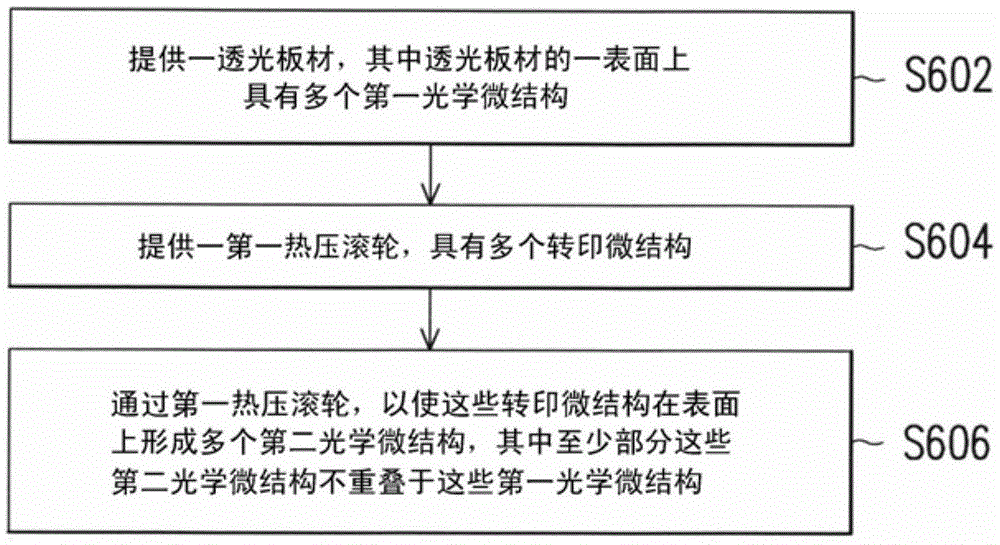
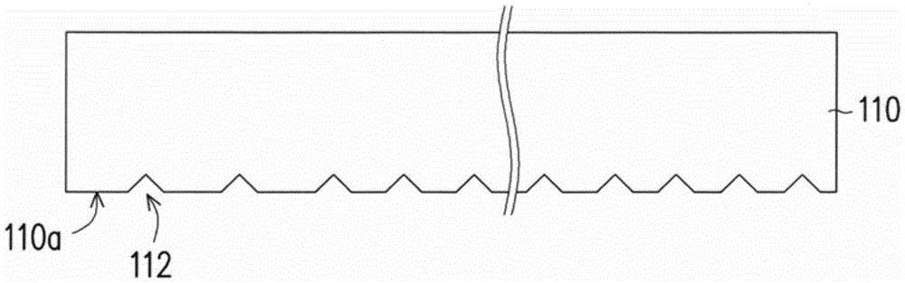
[0026] figure 1 It is a flowchart of a manufacturing method of a light guide plate according to an embodiment of the present invention. Figure 2A to Figure 2D is showing figure 1 Schematic diagram of the steps in the fabrication method. Please refer to Figure 1 to Figure 2D , first, provide Figure 2A A light-transmitting plate 110 is shown, wherein there are a plurality of first optical microstructures 112 on a surface 110a of the light-transmitting plate 110 (step S602), the thickness...


PUM


Abstract

The invention discloses a manufacturing method of a light guide plate. A transparent plate is provided, wherein a surface of the transparent plate has a plurality of first optical microstructures. Then, a first hot pressing roller having a plurality of transfer printing microstructures is provided. A plurality of second optical microstructures are formed on the surface through the transfer printing microstructures by the first hot pressing roller. At least a part of the second optical microstructures is not overlapped with the first optical microstructures. Thus, not only the first optical microstructures with complex shapes can be precisely formed through the injection molding process, but also optical and display optimization toward the backlight module can be performed by the second optical microstructures with simple shapes, so as to save production time.

Description

technical field [0001] The invention relates to a method for manufacturing a light guide plate applied to a backlight module, and in particular to a method for manufacturing a light guide plate and its optical microstructure. Background technique [0002] Current electronic devices mostly use flat panel display modules to display images, among which the technology of liquid crystal display modules is relatively sophisticated and popular. However, since the display panel of the liquid crystal display module itself cannot emit light, a backlight module is provided under the display panel to provide light required for displaying images. The backlight module uses the light guide plate to guide the light emitted by the light source arranged on the light incident surface of the light guide plate to the light output surface of the light guide plate, so as to form a uniform surface light source. [0003] Generally speaking, optical microstructures can be formed on the surface of th...

Claims


Application Information

Patent Timeline
Patent Type & Authority Applications(China)
IPC IPC(8): G02B6/00
CPCG02B6/0015G02B6/0043G02B6/0065B29C59/04B29C69/001B29C2059/023B29D11/00721B29D11/00932B29K2105/256B29K2995/0026G02B6/0036
Inventor 郭浩然刘时维
Owner NANO PRECISION TAIWAN LTD
Why Eureka
Try Eureka