Turning fixture

A fixture and turning technology, which is applied in the field of mechanical processing fixtures, can solve the problems of warping, low fixture clamping efficiency, and workpiece inequality, and achieve the effect of improving clamping efficiency and processing pass rate

Active Publication Date: 2014-02-19
CHANGSHA BODA MACHINERY PARTS CO LTD
View PDF10 Cites 21 Cited by
  • Summary
  • Abstract
  • Description
  • Claims
  • Application Information

AI Technical Summary

Problems solved by technology

[0011] The purpose of the present invention is to provide a turning fixture to solve the problem of low fixture clamping efficiency in turning processing, and the unevenness and warping of the workpiece due to improper clamping, resulting in unqualified product dimensions; to ensure that the workpiece is correctly clamped , improve the clamping efficiency and processing pass rate

Method used


Image

  • Turning fixture
  • Turning fixture
  • Turning fixture

Examples


Embodiment Construction

[0027] In order to enable those skilled in the art to better understand the technical solution of the present invention, the present invention will be described in detail below in conjunction with the accompanying drawings. The description in this part is only exemplary and explanatory, and should not have any limiting effect on the protection scope of the present invention. .

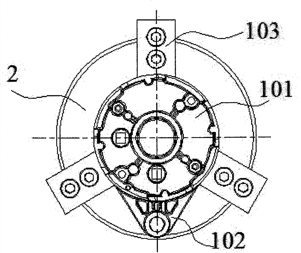
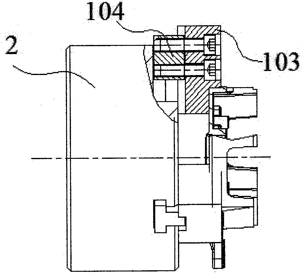
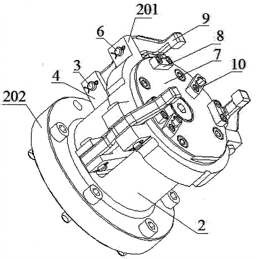
[0028] Such as Figure 3-Figure 7 As shown, a turning fixture, it includes a body 2, the body 2 is a hollow cylindrical structure, the front end of which extends outwards and is provided with three supporting feet 201, and the end part of which extends outwards to form a flange seat 202; the body 2 The front end is fixed with a positioning plate 7, and the positioning plate 7 is provided with two positioning pins 10 and 3 support blocks 8, which are evenly arranged on the end surface of the positioning plate 7; the center of the end of the body 2 is provided with a pull rod groove 203, It is equipped ...


PUM


Abstract

The invention discloses a turning fixture, and belongs to the field of machining fixtures. The turning fixture comprises a body (2), a positioning disc (7), positioning pins (10), a supporting block (8) and a pulling pressing mechanism, wherein the positioning pins (10) and the supporting block (8) are arranged on the positioning disc (7); and the pulling pressing mechanism consists of a pull rod (1), a short hinged shaft (3), a lever (4), a bush (5), a long hinged shaft (6) and a hook-shaped pressing plate (9). By the turning fixture, problems that in turning machining, the clamping efficiency of a fixture is low, workpieces are not flat or tilt due to improper clamping, and products are out-of-size are solved; actual clamping of the workpieces is guaranteed; and the clamping efficiency and the machining yield are improved.

Description

technical field [0001] The invention relates to a machining fixture, in particular to a turning fixture. Background technique [0002] In the machining industry, turning is a commonly used machining method. Fixtures are used when the workpiece needs to be fixed during machining operations. Such as Figure 1-Figure 2 As shown, the traditional clamping scheme is to use a three-jaw clamp for clamping; the body 2 is installed on the rotating spindle of the lathe, and the T-shaped block 104 adjusts the telescopic position of the clamp claw 103 so that the positioning surface of the workpiece 101 is aligned with the three clamp claws 103 The locating surface of the workpiece is fit and clamped, and the workpiece hanging angle 102 must avoid the clamp jaw 103. In this clamping method, since the clamp claws 103 have no directional reference, the operator has to visually avoid the clamp to interfere with the clamped workpiece, and the clamping efficiency is low; and the directions ...

Claims


Application Information

Patent Timeline
Patent Type & Authority Applications(China)
IPC IPC(8): B23Q3/00
CPCB23Q3/12
Inventor 杨潇
Owner CHANGSHA BODA MACHINERY PARTS CO LTD
Why Eureka
Try Eureka