Positioning sliding trolley capable of automatically tracking central line of rail in real time

A track center and sliding trolley technology, which is applied in the field of equipment boundary detection in the rail transit area, can solve the problems of inability to achieve continuous inspection, obvious left and right shaking of the inspection template, and low work efficiency.

Active Publication Date: 2014-02-19
罗汇智
View PDF7 Cites 1 Cited by
  • Summary
  • Abstract
  • Description
  • Claims
  • Application Information

AI Technical Summary

Problems solved by technology

Due to the comprehensive influence of the wheel-rail gap and lateral dynamic displacement on the moving flatbed, the inspection template shakes obviously from side to side (about 10-20mm), which is likely to cause missed inspections or misjudgments, so the inspection effect is not good
The defects of this method are mainly manifested in the fact that the flatbed car cannot realize the real-time coincidence of the centerline of the inspection template and the centerline of the track
The inspection and me

Method used


Image

  • Positioning sliding trolley capable of automatically tracking central line of rail in real time
  • Positioning sliding trolley capable of automatically tracking central line of rail in real time

Examples


Embodiment Construction

[0028] The specific implementation of the positioning trolley that automatically tracks the center line of the track in real time according to the present invention will be described in detail below in conjunction with the accompanying drawings.

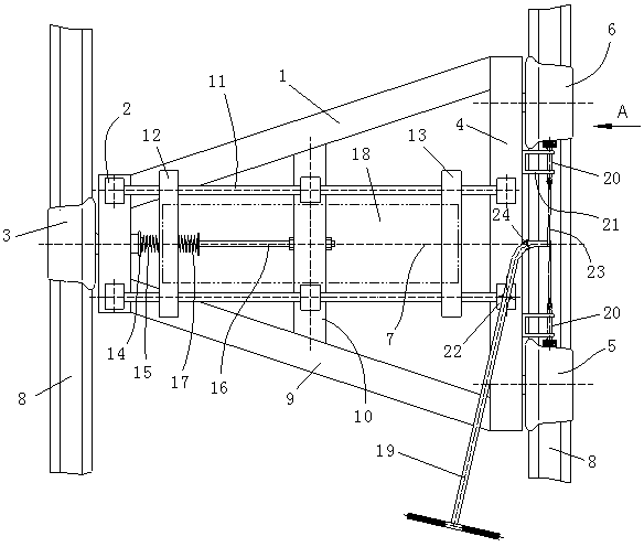
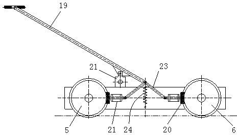
[0029] See attached figure 1 , 2 The vehicle frame 1 of the positioning trolley of the automatic real-time tracking track center line is a plane isosceles trapezoidal structure, and a short beam 2 is arranged on the left side of the vehicle frame 1, and the first traveling wheel 3 is arranged on the short beam 2 through a rolling bearing, The wheel shaft of the first running wheel 3 can elastically move in a small range in its axial direction, and the second running wheel 5 and the third running wheel 6 are respectively arranged through rolling bearings at the front and rear ends of the long beam 4 of the vehicle frame 1. The wheel 3 is located on the symmetry axis 7 of the isosceles trapezoid, the second running wheel 5 and the thi...


PUM


Abstract

The invention relates to the technical field of rail area equipment limit detection of rail traffic, and provides a positioning sliding trolley capable of automatically tracking the central line of a rail in real time. The positioning sliding trolley capable of automatically tracking the central line of the rail in real time comprises a trapezoid vehicle frame, wherein a first walking wheel is arranged at a left end beam of the vehicle frame, a second walking wheel and a third walking wheel are arranged at a right end beam of the vehicle frame, a middle longitudinal beam is arranged in the middle of the vehicle frame, two linear guide rails are arranged on the vehicle frame, a primary micro moving sliding block and a secondary micro moving sliding block are arranged on the two linear guide rails, a main shaft end portion of the first walking wheel penetrates out of a linear bearing hole embedded in the left end beam, a limiting retaining shoulder is arranged at the end portion of the main shaft end portion, a pre-tightening adjusting rod is arranged on the middle longitudinal beam, two pressure springs of the same rigidity are arranged between the limiting retaining shoulder and the primary micro moving sliding block and between the primary micro moving sliding block and the pre-tightening adjusting rod respectively, and the primary micro moving sliding block and the secondary micro moving sliding block are respectively provided with a detection device. By means of the positioning sliding trolley capable of automatically tracking the central line of the rail in real time, the walking wheels are attached to the steel rail, and efficient, continuous and accurate detection positioning of two different kinds of measuring bases is achieved.

Description

technical field [0001] The invention relates to the technical field of equipment limit detection in a rail transit track area, in particular to a positioning trolley that automatically tracks the center line of a track in real time. Background technique [0002] A lot of equipment needs to be arranged in the track area along the subway project. The limit positions of these devices to the inside are defined based on the centerline of the track, that is, the device limit. In order to ensure the safe operation of subway vehicles, the installation of these devices must not intrude into the limited area of ​​the equipment, otherwise the moving vehicle will easily collide with the equipment. Therefore, it is necessary to check whether the actual construction and installation equipment has invaded the limited area before the new line is opened for operation. In order to realize full-section and continuous high-efficiency inspection, it is usually carried out by pushing and install...

Claims


Application Information

Patent Timeline
IPC IPC(8): E01B35/04
Inventor 罗汇智
Owner 罗汇智
Why Eureka
Try Eureka