Small-size spacecraft butt-joint mechanism

A docking mechanism and spacecraft technology, applied in the direction of aerospace vehicle docking devices, etc., can solve the problems of difficult control, low positioning accuracy, severe collision, etc., and achieve the effect of stable and reliable transmission, high positioning accuracy, and high control accuracy

Active Publication Date: 2014-03-12
HARBIN INST OF TECH +1
View PDF6 Cites 67 Cited by
  • Summary
  • Abstract
  • Description
  • Claims
  • Application Information

AI Technical Summary

Problems solved by technology

[0007] The present invention provides a docking mechanism for small spacecraft to solve the problems of severe collision in the docking proc

Method used


Image

  • Small-size spacecraft butt-joint mechanism
  • Small-size spacecraft butt-joint mechanism
  • Small-size spacecraft butt-joint mechanism

Examples


specific Embodiment approach 1

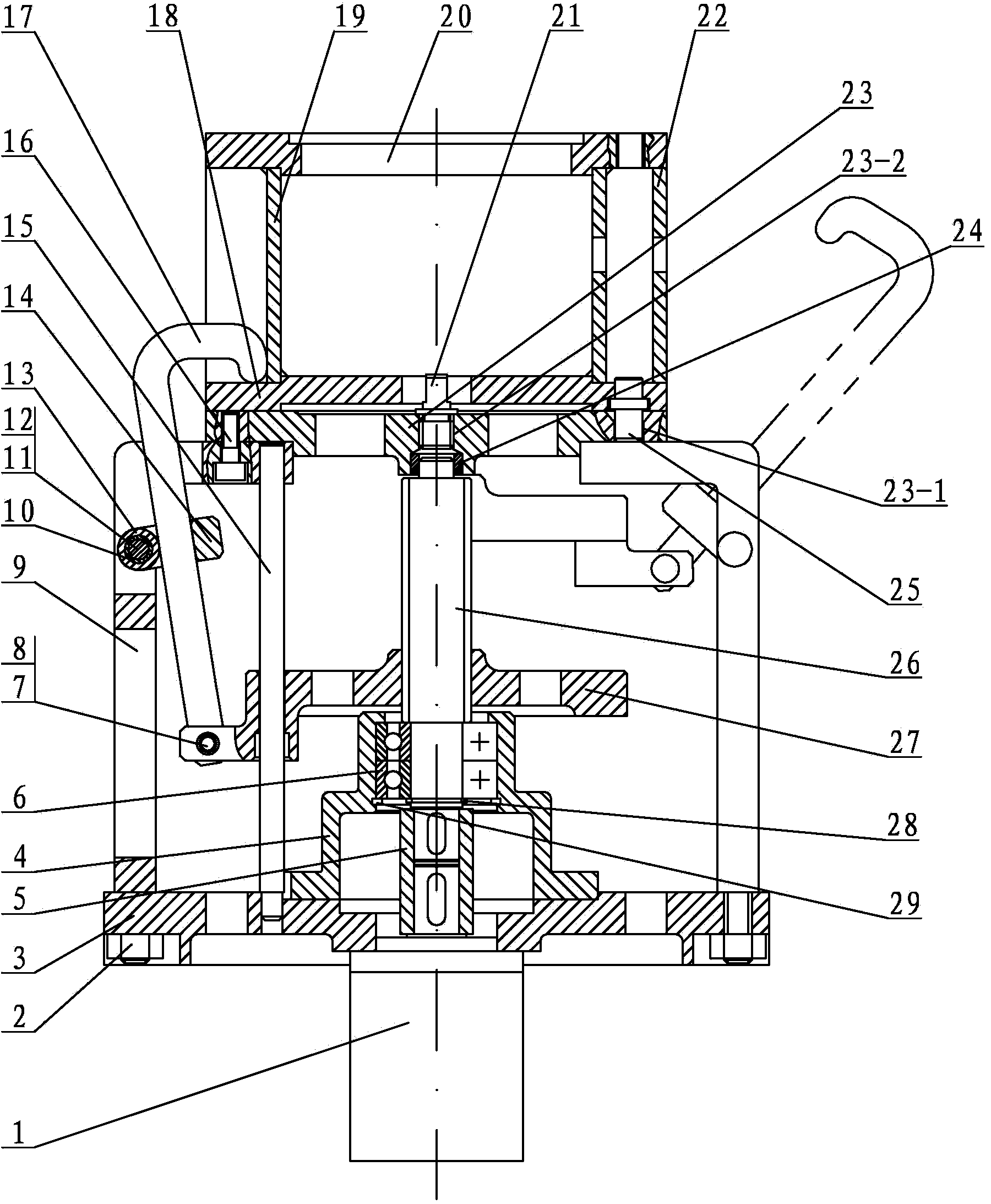
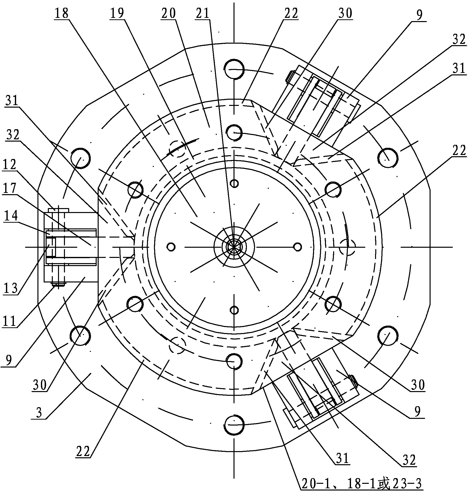
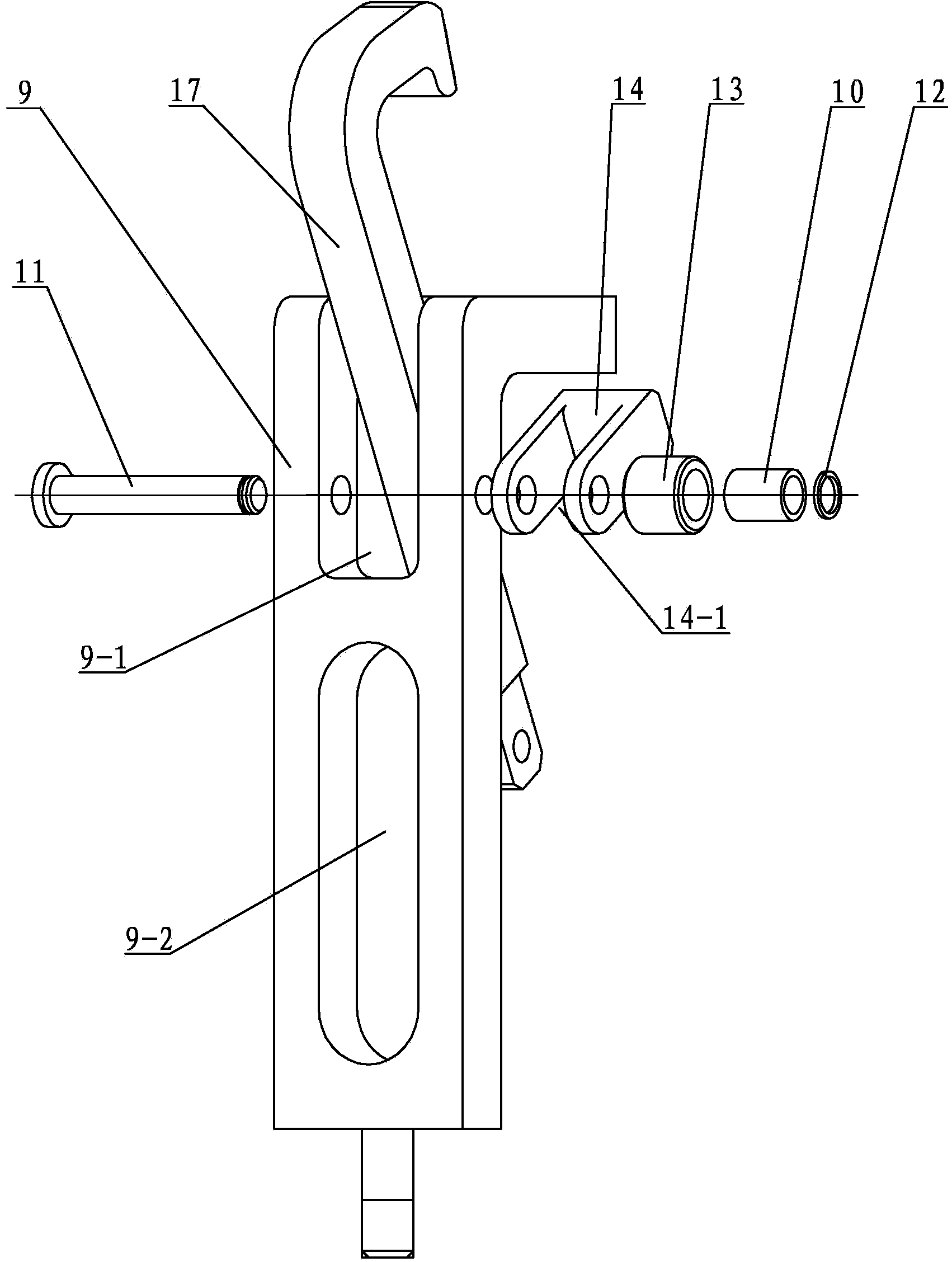
[0012] Specific implementation mode one: combine Figure 1 ~ Figure 3 Describe this embodiment, this embodiment includes an active connection mechanism and a passive connection mechanism, the passive connection mechanism includes a passive lower plate 18, a connecting sleeve 19, a passive upper plate 20, three arc-shaped coaming plates 22, three positioning pins 25, Three first guide plates 30 and three second guide plates 31, the passive upper plate 20 and the passive lower plate 18 are arranged horizontally and facing each other up and down, and the connecting sleeve 19 and the three arc-shaped shrouds 22 are all arranged on the passive upper plate 20 and the passive lower plate 18, the connecting sleeve 19, the passive upper plate 20 and the passive lower plate 18 are coaxially arranged, the upper end of the connecting sleeve 19 is connected with the passive upper plate 20, and the lower end of the connecting sleeve 19 is connected with the passive lower plate. The disc 18 ...

specific Embodiment approach 2

[0013] Specific implementation mode two: combination figure 1 Describe this embodiment, the passive lower wall 18, the passive upper wall 20, the active lower wall 3 and the active upper wall 23 of this embodiment are all arranged coaxially. This design makes the structure more reasonable, facilitates the connection of active and passive parts, simplifies the transmission process, and improves the transmission efficiency. Other components and connections are the same as those in the first embodiment.

specific Embodiment approach 3

[0014] Specific implementation mode three: combination figure 1 and Figure 4The present embodiment will be described. The diameter of the passive upper wall 20 and the diameter of the passive lower wall 18 in this embodiment are set to be equal. This design makes the structure more reasonable. Other compositions and connections are the same as those in Embodiment 1 or 2.


PUM


Abstract

The invention discloses a small-size spacecraft butt-joint mechanism, relates to a spacecraft butt-joint mechanism and aims at solving the problems that an existing small-size spacecraft butt-joint mechanism is fierce in collision, low in positioning precision, and large in control difficulty in the butt-joint process and unstable enough after butt-joint. A connecting sleeve and three arc-shaped enclosing plates are arranged between an upper driven disc and a lower driven disc; a first guide plate is arranged at one end of each arc-shaped enclosing plate; a second guide plate is arranged at the other end of each arc-shaped enclosing plate; the adjacent first guide plates and three second guide plates form a V-shaped positioning slot; three brackets are uniformly distributed between the upper drive disc and the lower drive disc along the same circumference; a stepped motor is fixed in the center of the lower drive disc; the stepped motor is connected with a lead screw; a threaded lifting disc is screwed on the lead screw; the lower end of each locking claw penetrates through a slide path and is hinged with the threaded lifting disc, and each locking claw is contacted with the surface of a roller; the upper end of each locking claw is arranged in the corresponding V-shaped positioning slot. The small-size spacecraft butt-joint mechanism disclosed by the invention is mainly used for capturing and butt-joint of a small-size spacecraft.

Description

technical field [0001] The invention relates to a docking mechanism for a spacecraft, in particular to a docking mechanism for a small spacecraft. Background technique [0002] With the rapid development of the aerospace industry in the new century, countries have successively developed and launched a large number of spacecraft for various mission requirements. The structure and composition of spacecraft have become increasingly complex, and their performance and technical level have been continuously improved. Under such circumstances, a complete set of on-orbit service technologies is required to ensure a more durable, stable, and high-quality on-orbit operation of the spacecraft in a complex space environment. The execution of all on-orbit service missions is based on the rendezvous, accompanying / orbiting and docking of the service spacecraft and the target spacecraft. The successful rendezvous and docking of the two spacecraft is a prerequisite for the smooth execution o...

Claims


Application Information

Patent Timeline
IPC IPC(8): B64G1/64
Inventor 魏承刘天喜马聪潘冬田浩赵阳
Owner HARBIN INST OF TECH
Why Eureka
Try Eureka